How Do I Account for Mandrel Offset in Simulation?
What is mandrel offset?
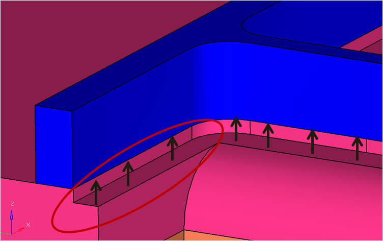
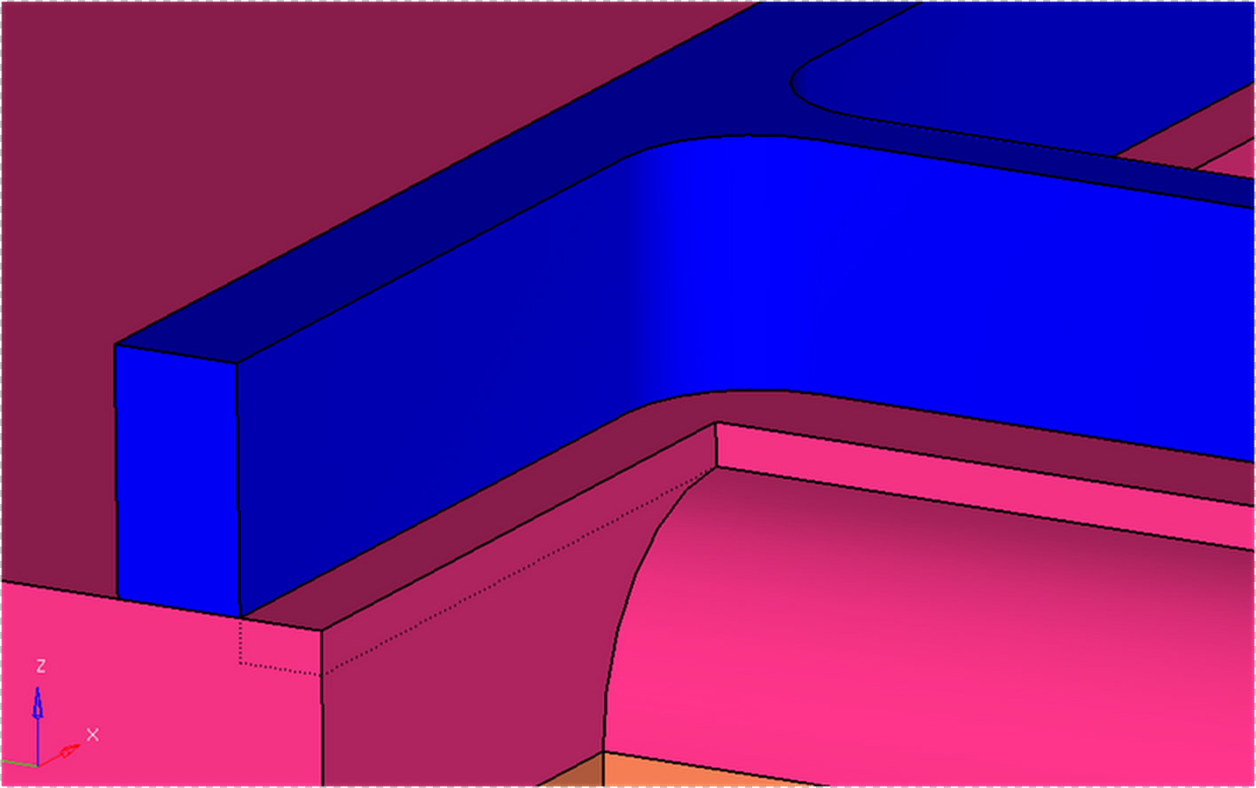
For any hollow dies, the bearing on the mandrel (or inner bearing ) starts before the bearing on the die ( or outer bearing). This is to account for mandrel shift or movement that occurs due to extrusion forces during extrusion process. The distance between bearing start locations between inner and outer bearing is called the mandrel offset.
How to account for mandrel offset?
Option-2:
The user can also mesh the model with the mandrel offset, and the solver will account for this step in the computation and the computed solution will be equally accurate. The advantage of including mandrel offset is savings in time spent in CAD correction; however, there may be a disadvantage in creating good quality mesh in this region.
Here is one example - how to update the BC for mandrel offset.
Bearing BearingHole1Inner1 {
Bearing_Profile = "prof_BearingHole1Inner1"
FrictionModel = "Viscoplastic"
HeatFlux = 0
MandrelOffset = 1.0
#Material = AA6063
}