Set up a mounting bracket model and run topography optimization to minimize the mass
of the bracket.
In this lesson you will learn how to:
Create fasteners and define contacts
Create local forces in the X and Y directions
Create local displacement constraints
Define multiple load cases
Apply a symmetry plane
Run a topology optimization to minimize mass
Open the Mounting Bracket Model
Press F7 to open the Demo Browser.
Double-click the Mounting_Bracket.stmod file to load it in
the modeling window.
Set the display units in the Unit System Selector to
MMKS (mm kg N s).
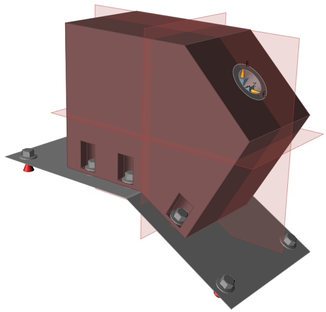
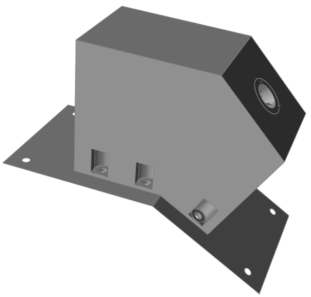
Use the right mouse button and the middle
mouse button to pan and rotate the view so the mounting bracket
is positioned as shown below:
Create Fasteners and Define Contacts
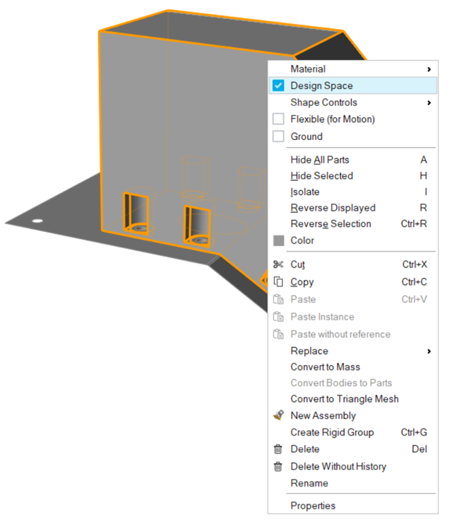
Right-click on the large solid and select Design
Space.
Note: Notice the solid bosses within the larger solid. This model has already
been partitioned to facilitate proper loading and connections, which is
recommended when running an optimization.
On the Structures ribbon, select the
Fasteners tool.
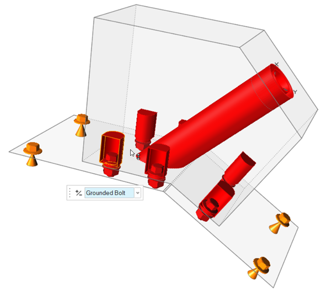
Locations with aligned holes where fasteners can be placed are shown in red. On
the guide bar, click the Create All Fasteners button to create fasteners in all of
the red locations.
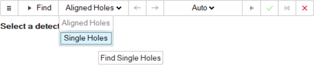
Click Aligned Holes on the guide bar and select
Single Holes from the dropdown menu.
In the modeling window, select the four single holes on the 2D plate. Because
the holes are single, the fasteners are created as grounded bolts.
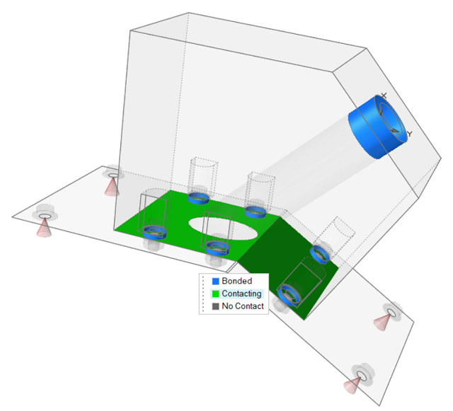
Next, select the Contacts tool.
Select the large flat contact between the design space and the plate, then
choose Contacting on the microdialog.
Right-click and mouse through the check mark to exit, or double-right-click.
Create Forces in the Local System
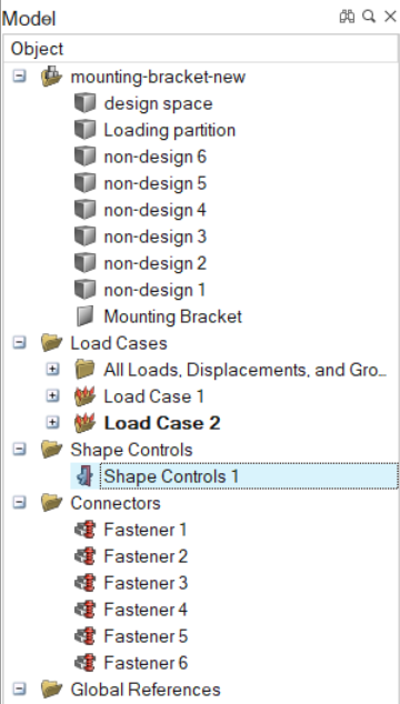
Press F2 to open the Model Browser.
Right-click the part named Loading Partition and select
Isolate from the context menu.
Right-click System 1 and select
Show from the context menu.
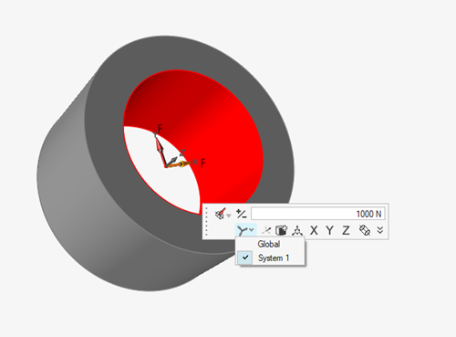
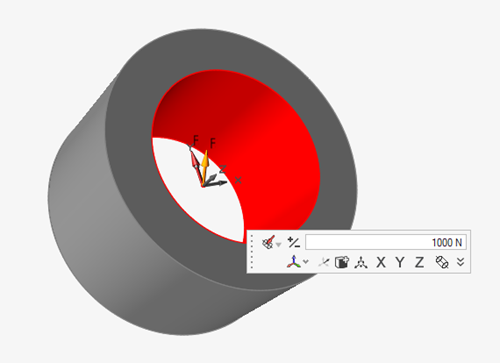
Select the Force tool on the Loads icon.
Select the inner surface of the Loading Partition part
and enter 1000 N for the force value.
On the microdialog, click the icon and select System 1
from the dropdown menu.
On the microdialog, click X to align the force with the
X axis of the local system.
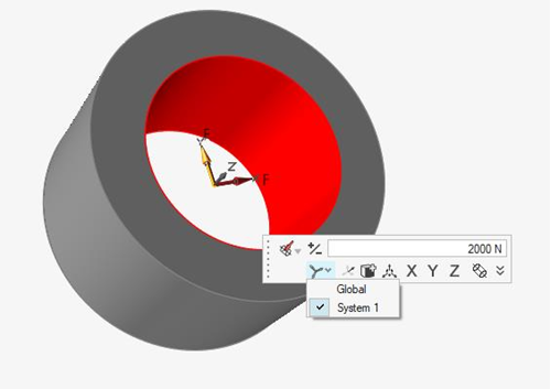
On the Loading Partition part, select the same inner surface to create a second
force and enter 2000 N for the force value.
In the microdialog, click the icon and select System 1
from the dropdown menu.
In the microdialog, click the Y button to align the
force with the Y axis of the local system.
Right-click and mouse through the check mark to exit, or double-right-click.
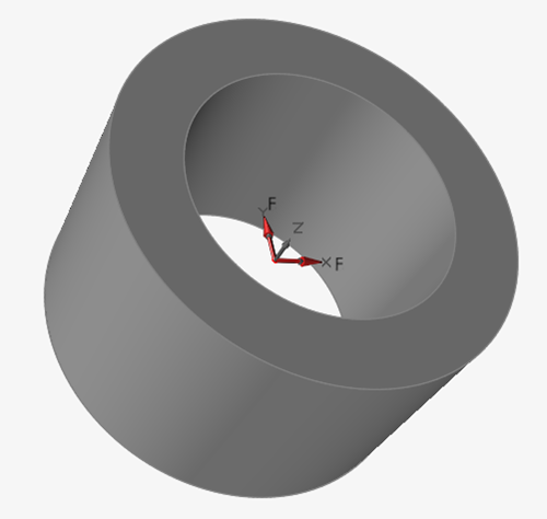
Note: when you are finished with this step, Force 1 will
be aligned with local X and have a value of 1000 N and Force 2 will be
aligned with local Y and have a value of 2000 N.
Create Displacement Constraints in the Local System
Note: Displacement constraints are typically obtained by running
an analysis of the full design space.
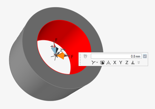
Select the Displacement Constraint tool on the
Disps icon.
Select the inner surface of the Loading Partition.
In the microdialog, enter 0.8 mm for the displacement
constraint.
Click the icon and select System 1
from the dropdown menu.
Click the X button to align the displacement constraint
with the X axis of the local system.
Repeat steps 2 - 4 to create a second displacement constraint, then click the
Y button to align it with the local system's Y
axis.
Right-click and mouse through the check mark to exit, or double-right-click.
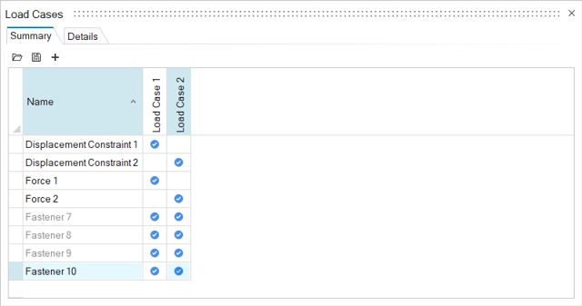
Create Load Cases
Select the List Load Cases tool on the
Loads icon to open the Load Cases table.
Right-click in the header area of the table and select New Load
Case from the context menu to create Load Case 2. You should now
have two load cases.
For Load Case 1, ensure that the following items are selected:
Displacement Constraint 1
Force 1
Fastener 7
Fastener 8
Fastener 9
Fastener 10
For Load Case 2, ensure that the following items are selected:
Displacement Constraint 2
Force 2
Fastener 7
Fastener 8
Fastener 9
Fastener 10
Close the Load Cases table.
Add Symmetry Planes
Press the A key to display all. If necessary, press the
F key to fit the model in the modeling window.
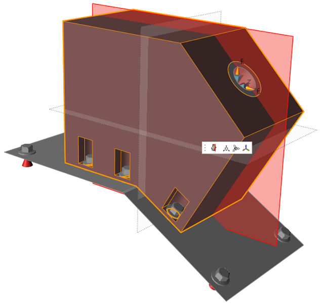
Select the Symmetric Controls tool on the
Shape Controls icon.
Select the Symmetric tool from the secondary
ribbon.
Select the bracket in the modeling window. Shape Controls 1 is added to the
Shape Controls folder in the Model Browser.
Click the transparent red planes aligned with the Y and Z axes to deselect
them.
Right-click and mouse through the check mark to exit, or double-right-click.
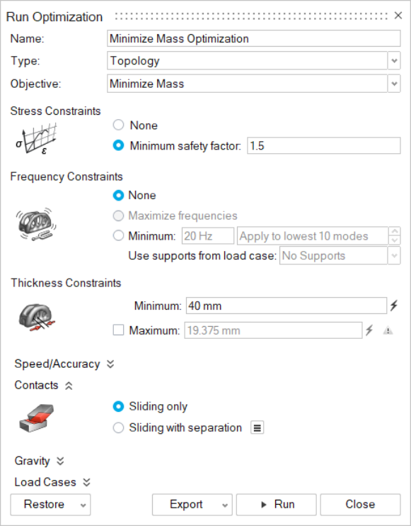
Run an Optimization to Minimize Mass
Select the Run Optimization tool on the
Optimize icon.
In the Run Optimization window, enter a Name for the
optimization run.
Select Minimize Mass for the
Objective.
Confirm that the Minimum safety factor is set to
1.5.
Confirm that the Thickness Constraints Minimum is set to
40 mm.
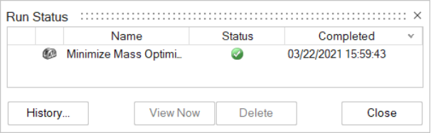
Click Run. A green check mark appears in the
Run Status window when the optimization is
complete.
Note: If you don't want to wait for the run to complete,
double-click the Mounting_Bracket_run.stmod file in the
Demo Browser to open it in the modeling window, then click Show
Analysis Results on the Analyze icon to load the
results.
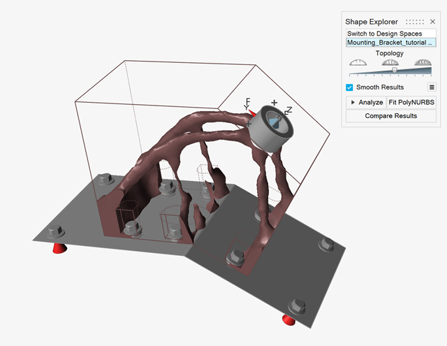
In the Run Status window, double-click the name of the run to view the results.
The optimized shape is displayed in the modeling window and is listed as an
alternative in the Shape Explorer.
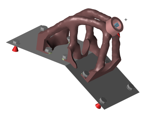
Drag the topology slider on the Shape Explorer until all sections are
continuous and solid.

 Create All Fasteners button to create fasteners in all of
the red locations.
Create All Fasteners button to create fasteners in all of
the red locations.


 icon and select System 1
from the dropdown menu.
icon and select System 1
from the dropdown menu.