Tutorial: Optimizing Lattice
Generate a PolyNURBS from an optimized shape, then run and review a lattice optimization.
In this lesson, you will:
- Run an initial topology optimization
- Generate a PolyNURBS from an optimized shape
- Set the element size for the new design space
- Run a lattice optimization
- Review lattice results
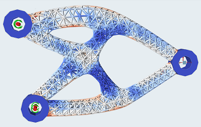
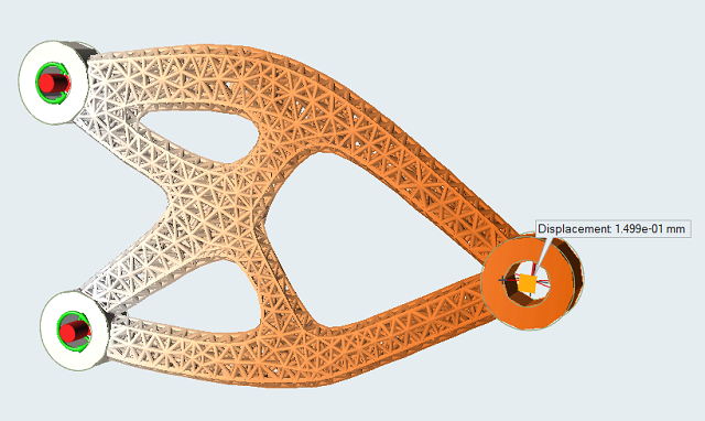
Figure 1. Lattice Optimization Results
Overview
Lattice structures typically consist of different types of cells. In Altair Inspire, each beam can be optimized, filling your design space with an optimized lattice structure rather than repetitive patterns. It only works on solids, and design spaces have to be separated with non-design space.
While unique to 3D printing, lattice structures bear several desirable characteristics from a design perspective. Due to the large network of structural members, optimized lattice designs tend to exhibit better stability and more desirable thermal behavior. They also have desirable weight characteristics, and are used as an approach to target weight reduction. Lattice designs are particularly well-suited to biomedical applications such as implants, as the porous nature of the structure facilitates bone and tissue growth.
A lattice structure occupying the same design space as a solid structure will be less stiff and have higher stresses. For this reason, it is often necessary to set your design requirements more conservatively than you normally would for a traditional topology optimization. It is not uncommon for displacements and stresses to be five to ten times greater in a lattice structure compared to that of a solid structure occupying the same region. As it is not always possible to have an accurate estimate of the degradation, it may be necessary to start the optimization with increasingly strict constraints before a desired result from the lattice optimization is obtained.
Run Topology Optimization
First, let's run an initial topology optimization on the design space of our example model. We'll use a stress constraint five times the desired performance for the final design, as the lattice occupying the optimal topology will have increased stress and displacement.
-
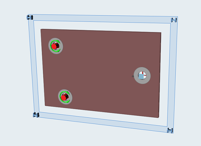
Double-click the 1.0_hanger_topology.stmod file to load it
in the modeling window.
Note that it is set up with a maximum displacement of 0.15 mm at the load application point. This will become important in the next step.
-
Click Run Optimization
 on the Optimize icon on the Structure ribbon.

-
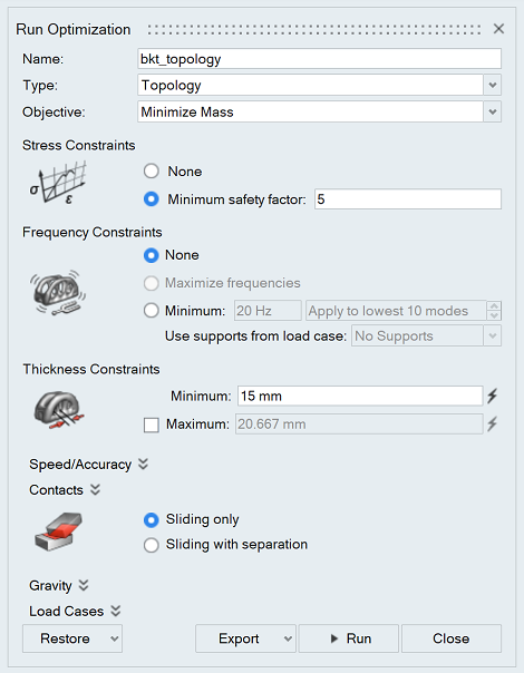
Set the options in the Run Optimization window as shown
below:
-
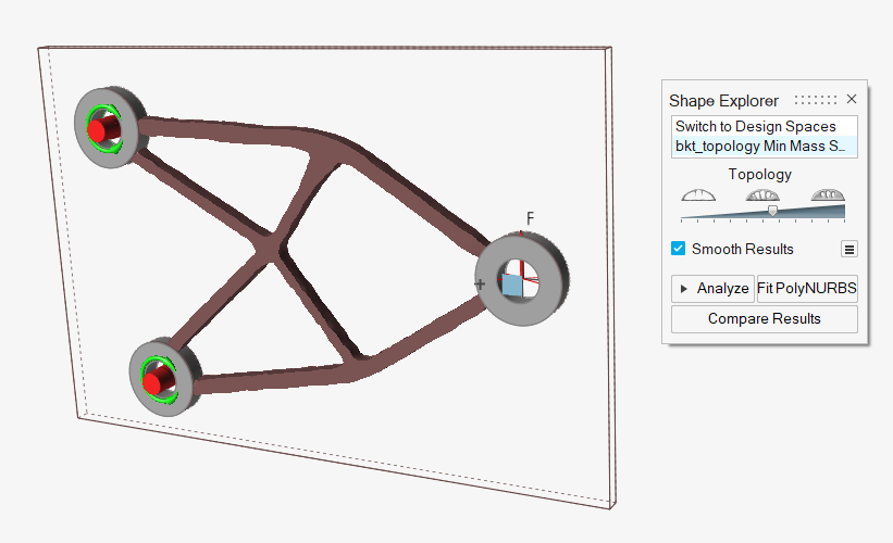
When the run is complete, double-click the run name to view the results.
(Alternatively, you can press F7 and double-click the
1.1_hanger_topology_run.stmod file in the Demo Browser
to load a file that includes the results.)
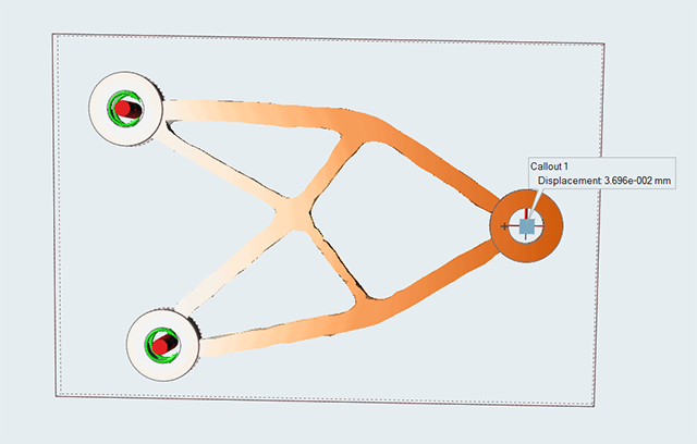
Run Analysis on the Optimized Result
Next, reanalyze the optimized result at different thresholds until the displacement at the load point is less than 0.02 mm (a fifth of the ultimate target).
-
Click the
 icon under Callouts and place a
callout on the load point.
icon under Callouts and place a
callout on the load point.
-
The displacement is greater than 0.02 mm, so click the Show
Optimization Results icon to return to the initial optimized
result.

-
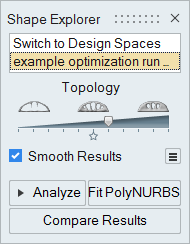
On the Shape Explorer, slide the topology slider to the right to increase the
threshold.
-
Double-right-click to exit the Analysis Explorer.
Generate a PolyNURBS Part from the Optimized Result
Use the PolyNURBS tools to create a new design space based on the topology results generated. (To skip this step, load the 2.0_hanger_lattice_PN.stmod file from the Demo Browser and proceed to step 5.)
-
Select PolyNURBS on the geometry ribbon.

-
Use Wrap and the other PolyNURBS tools as needed to
create a PolyNURBS part around the optimized shape.
-
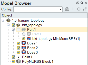
Deselect the check box next to Part 1 in the Model Browser to configure the
original design space off.
-
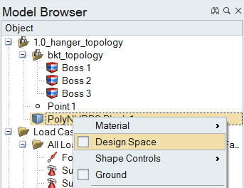
Right-click the PolyNURBS part and select Design Space from the context
menu.
-
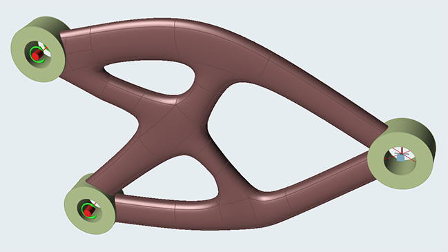
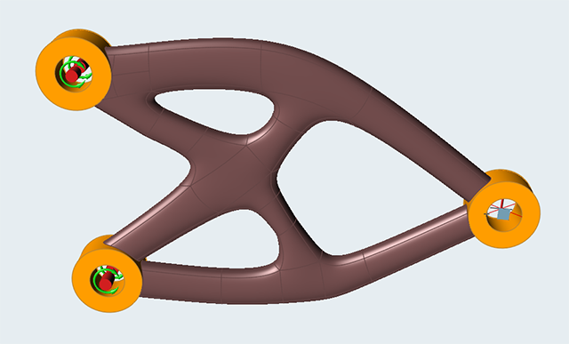
The PolyNURBS part that was fit to the baseline topology optimization results
is now the new design space.
-
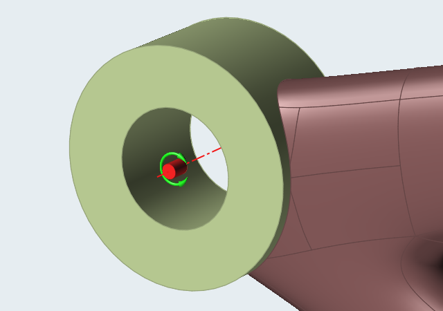
Note the slight offset of the design space from the non-design boss parts,
which prevents the resulting lattice from protruding.
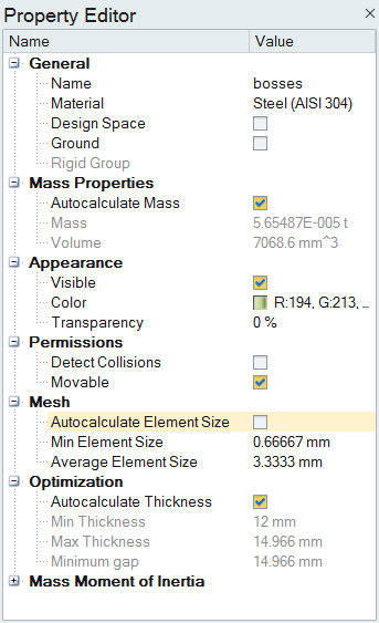
Turn Off Autocalculate Element Size
The target lattice length is often larger than the ideal element size for the non-design parts. So before running the lattice optimization, we'll turn off Autocalculate Element Size in the Property Editor.
-
Select the boss parts.
-
Deselect the Autocalculate Element Size check box in the
Property Editor.
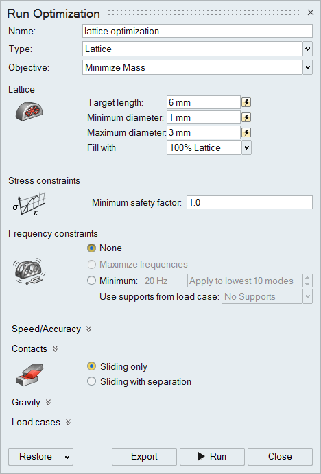
Set Up and Run Lattice Optimization
Now we'll run a lattice optimization. (To skip this step, load the 3.0_lattice_hanger_PN_RUN.stmod file from the Demo Browser and proceed to step 7.)
-
Click Run Optimization
 on the Optimize icon on the
Structure ribbon.
on the Optimize icon on the
Structure ribbon.
-
Set the options in the Run Optimization window as shown below:
-
When the run is complete, double-click the run name to view the results.
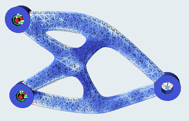
Review the Lattice Optimization Results
Review the results of the lattice optimization run in the previous step. Lattice optimization results appear in the Analysis Explorer rather than the Shape Explorer.
-
Click the icon under
Callouts and place a callout at the load point. Note
the value of .1499 mm is within the constraint of 0.15 mm.
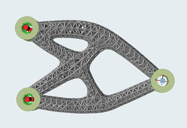
-
Click the
 icon under Show on the
Analysis Explorer to hide the contours.
icon under Show on the
Analysis Explorer to hide the contours.
-
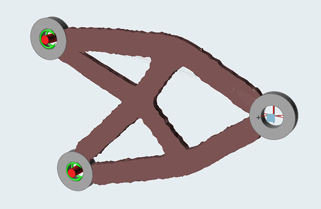
Click the
 icon and select
Smooth Lattice. This displays an alternate
visualization of the resulting lattice structure with radii between the lattice
beams.
icon and select
Smooth Lattice. This displays an alternate
visualization of the resulting lattice structure with radii between the lattice
beams.
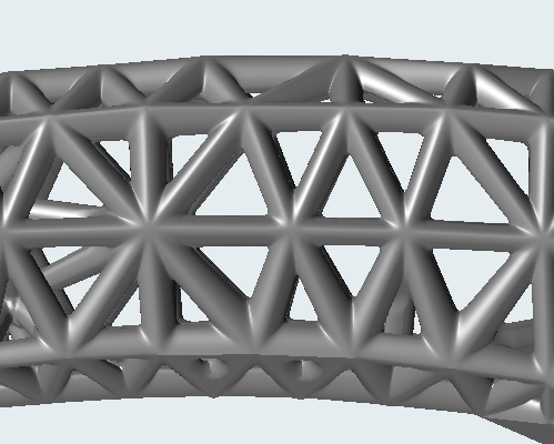 Figure 2. Smooth Lattice On
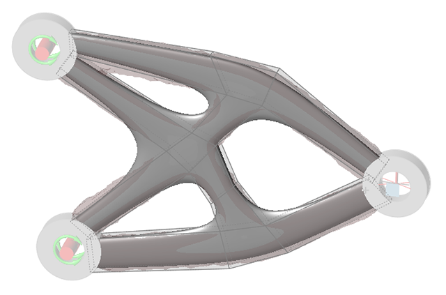
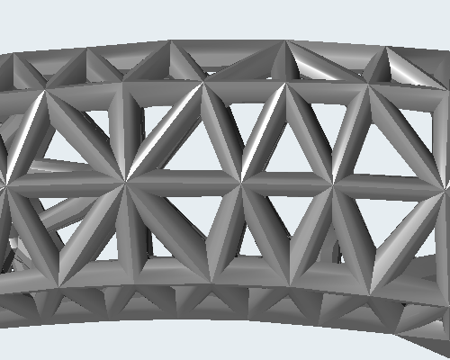 Figure 3. Smooth Lattice Off