Static Solution by Explicit Time Integration

Explicit algorithms are very useful for modeling a dynamic simulation. However, they cannot model a quasi-static or static simulation as easily. This is due to the fact that in an explicit approach, first the nodal accelerations are found by resolving the equilibrium equation at time t n MathType@MTEF@5@5@+= feaagKart1ev2aaatCvAUfeBSjuyZL2yd9gzLbvyNv2CaerbuLwBLn hiov2DGi1BTfMBaeXatLxBI9gBaerbd9wDYLwzYbItLDharqqtubsr 4rNCHbGeaGqiVu0Je9sqqrpepC0xbbL8F4rqqrFfpeea0xe9Lq=Jc9 vqaqpepm0xbba9pwe9Q8fs0=yqaqpepae9pg0FirpepeKkFr0xfr=x fr=xb9adbaqaaeGaciGaaiaabeqaamaabaabaaGcbaGaamiDamaaBa aaleaacaWGUbaabeaaaaa@380E@ . Other DOFs are then computed by explicit time integration. This procedure implies that the nodal acceleration must exist; however, some numerical methods may be employed for the simulation of a static process.

Slow Dynamic Computation

The loading is applied at a rate sufficiently slow to minimize the dynamic effects. The final solution is obtained by smoothing the curves.

In case of elasto-plastic problems, one must minimize dynamic overshooting because of the irreversibility of the plastic flow.

Dynamic Relaxation or Nodal Damping (/DYREL)

This method was first introduced by Otter 1 and has been used in several hydrodynamic codes. A nodal damping C υ MathType@MTEF@5@5@+= feaagKart1ev2aaatCvAUfeBSjuyZL2yd9gzLbvyNv2CaerbuLwBLn hiov2DGi1BTfMBaeXatLxBI9gBaerbd9wDYLwzYbItLDharqqtubsr 4rNCHbGeaGqiVu0Je9sqqrpepC0xbbL8F4rqqrFfpeea0xe9Lq=Jc9 vqaqpepm0xbba9pwe9Q8fs0=yqaqpepae9pg0FirpepeKkFr0xfr=x fr=xb9adbaqaaeGaciGaaiaabeqaamaabaabaaGcbaGaam4qaiabew 8a1baa@3885@ is added to the momentum equation:(1) M d ν d t + C υ = f e x t f int
The dashpot force is calculated by:(2) F c = C V
The internal force is calculated by:(3) F k = K X = F k t Δ t / 2 + K V Δ t (4) γ 0 = F k M
The total acceleration is given by:(5) γ 1 = γ 0 + F c M = γ 0 C V M (6) V t + Δ t / 2 = V t Δ t / 2 + γ 1 Δ t (7) V = V t Δ t / 2 + 1 2 γ 1 Δ t (8) V t + Δ t / 2 = V t Δ t / 2 + γ 0 Δ t C V M Δ t
You have:(9) V t + Δ t / 2 = V t Δ t / 2 + γ 0 Δ t C M ( V t Δ t / 2 + 1 2 γ 1 Δ t ) Δ t (10) V t + Δ t / 2 = ( 1 C Δ t M ) V t Δ t / 2 + ( γ 0 1 2 γ 1 Δ t C M ) Δ t (11) V t + Δ t / 2 = ( 1 C Δ t M ) V t Δ t / 2 + ( 1 Δ t C γ 1 M γ 0 ) γ 0 Δ t
Approximation γ 1 γ 0 = 1 after the variable is changed, ω = C Δ t 2 M , you obtain:(12) V t + Δ t / 2 = ( 1 2 ω ) V t Δ t / 2 + ( 1 ω ) γ 0 Δ t (13) ω = C Δ t 2 M C = 2 M ω Δ t
Which gives the expression of C MathType@MTEF@5@5@+= feaagKart1ev2aaatCvAUfeBSjuyZL2yd9gzLbvyNv2CaerbuLwBLn hiov2DGi1BTfMBaeXatLxBI9gBaerbd9wDYLwzYbItLDharqqtubsr 4rNCHbGeaGqiVu0Je9sqqrpepC0xbbL8F4rqqrFfpeea0xe9Lq=Jc9 vqaqpepm0xbba9pwe9Q8fs0=yqaqpepae9pg0FirpepeKkFr0xfr=x fr=xb9adbaqaaeGaciGaaiaabeqaamaabaabaaGcbaGaam4qaaaa@36BE@ as a proportional matrix to M MathType@MTEF@5@5@+= feaagKart1ev2aaatCvAUfeBSjuyZL2yd9gzLbvyNv2CaerbuLwBLn hiov2DGi1BTfMBaeXatLxBI9gBaerbd9wDYLwzYbItLDharqqtubsr 4rNCHbGeaGqiVu0Je9sqqrpepC0xbbL8F4rqqrFfpeea0xe9Lq=Jc9 vqaqpepm0xbba9pwe9Q8fs0=yqaqpepae9pg0FirpepeKkFr0xfr=x fr=xb9adbaqaaeGaciGaaiaabeqaamaabaabaaGcbaGaam4qaaaa@36BE@ with:(14)

C = A M and A = 2 ω Δ t

or(15) A = 2 β Τ (16) ω = β Δ t Τ
Combining Equation 14 and Equation 15, and you obtain:(17) C = 2 β M Τ

Where, β is the relaxation coefficient whose recommended value is 1. T MathType@MTEF@5@5@+= feaagKart1ev2aaatCvAUfeBSjuyZL2yd9gzLbvyNv2CaerbuLwBLn hiov2DGi1BTfMBaeXatLxBI9gBaerbd9wDYLwzYbItLDharqqtubsr 4rNCHbGeaGqiVu0Je9sqqrpepC0xbbL8F4rqqrFfpeea0xe9Lq=Jc9 vqaqpepm0xbba9pwe9Q8fs0=yqaqpepae9pg0FirpepeKkFr0xfr=x fr=xb9adbaqaaeGaciGaaiaabeqaamaabaabaaGcbaGaam4qaaaa@36BE@ is less than or equal to the highest period of the system. These are the input parameters used in /DYREL option.

The explicit time integration scheme is changed to compute the new velocities. The explicit time integration in Dynamic Analysis gives (Central Difference Algorithm, Equation 7):(18) V t + Δ t / 2 = V t Δ t / 2 + γ t Δ t
which is now written as: (19) V t + Δ t / 2 = ( 1 2 ω ) V t Δ t / 2 + ( 1 ω ) γ t Δ t
Where,(20) ω = β Δ t Τ

Energy Discrete Relaxation

This empirical methodology consists in setting to zero the nodal velocities each time the Kinetic Energy reaches a maximum.

The loading is applied at a rate sufficiently slow to minimize the dynamic effects. The final solution is obtained by smoothing the curves.

In case of elasto-plastic problems, one must minimize dynamic overshooting because of the irreversibility of the plastic flow.

Rayleigh Damping (/DAMP)

In this method a proportional damping matrix is defined as:(21) [ C ] = α [ M ] + β [ K ]

Where, α and β are the pre-defined constants. In modal analysis, the use of a proportional damping matrix allows to reduce the global equilibrium equation to n-uncoupled equations by using an orthogonal transformation.

If the global equilibrium equation is expressed as:(22) [ M ] { X ¨ } + [ C ] { X ˙ } + [ K ] { X } = { F t }
The transformed uncoupled system of equations can be written as:(23)
With (24) [ φ ] T [ C ] [ φ ] = [ α + β ω 1 2 0 . . 0 0 α + β ω 2 2 . . 0 . . . . . . . . . . 0 . . . α + β ω n 2 ]
Each uncoupled equation is written as:(25) ξ ¨ i + 2 ω i ζ i ξ ˙ i + ω i 2 ξ i = f i t
With (26) 2 ζ i ω i = α + β ω i 2
Where,
ω i
The ith natural frequency of the system
ζ i
The ith damping ratio
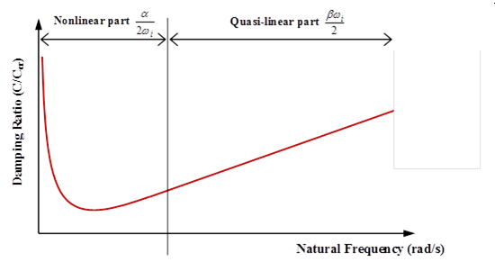
This leads to a system of n equations with two unknown variables α and β . Regarding to the range of the dominant frequencies of system, two frequencies are chosen. Using the pair of the most significant frequencies, two equations with two unknown variables can be resolved to obtain values for α and β . For high frequencies the role of β is more significant. However, for lower frequencies α plays an important role (Figure 1).


Figure 1. Rayleigh Damping Variation for Natural Frequencies
The Rayleigh damping method applied to explicit time-integration method leads to the following equations:(27) M γ t + C v t = F e x t t F int t
With C = α M + β K (28) F int t = F int t d t + K v t d t 2 d t (29) v t = v t d t 2 + γ t d t 2 (30) M γ 0 t = F e x t t F int t
Neglecting F e x t t F e x t t d t and v t v t d t 2 , in β K v t evaluation you have:(31) K v t = K v t d t 2 = F int t F int t d t d t M ( γ 0 t γ 0 t d t ) d t
And finally:(32) γ 0 t = M 1 ( F e x t t F int t ) (33) γ t = γ 0 α v t d t 2 β d t ( γ 0 t γ 0 t d t ) 1 + α d t 2 (34) v t + d t 2 = v t d t 2 + γ t d t

The three approaches available in Radioss are Dynamic Relaxation (/DYREL), Energy Discrete Relaxation (/KEREL) and Rayleigh Damping (/DAMP). Refer to Example Guide for application examples.

The loading is applied at a rate sufficiently slow to minimize the dynamic effects. The final solution is obtained by smoothing the curves.

In case of elasto-plastic problems, one must minimize dynamic overshooting because of the irreversibility of the plastic flow.

Acceleration Convergence

For every method, an acceleration of the convergence to the static solution is desirable. The constant time step is one of the more usual methods. In fact, in quasi-static analysis, the duration of the study is proportional to the maximum period of the structure. The total number of computation cycles is then proportional to the ratio T dt MathType@MTEF@5@5@+= feaagKart1ev2aaatCvAUfeBSjuyZL2yd9gzLbvyNv2CaerbwvMCKf MBHbqefqvATv2CG4uz3bIuV1wyUbqedmvETj2BSbqefm0B1jxALjhi ov2DaebbnrfifHhDYfgasaacH8srps0lbbf9q8WrFfeuY=Hhbbf9v8 qqaqFr0xc9pk0xbba9q8WqFfea0=yr0RYxir=Jbba9q8aq0=yq=He9 q8qqQ8frFve9Fve9Ff0dmeaacaGacmGadaWaaiqacaabaiaafaaake aadaWcaaqaaiaadsfaaeaacaWGKbGaamiDaaaaaaa@3BA2@ .

Where,
T MathType@MTEF@5@5@+= feaagKart1ev2aaatCvAUfeBSjuyZL2yd9gzLbvyNv2CaerbuLwBLn hiov2DGi1BTfMBaeXatLxBI9gBaerbd9wDYLwzYbItLDharqqtubsr 4rNCHbGeaGqiVu0Je9sqqrpepC0xbbL8F4rqqrFfpeea0xe9Lq=Jc9 vqaqpepm0xbba9pwe9Q8fs0=yqaqpepae9pg0FirpepeKkFr0xfr=x fr=xb9adbaqaaeGaciGaaiaabeqaamaabaabaaGcbaGaam4qaaaa@36BE@
Largest period of the structure
dt MathType@MTEF@5@5@+= feaagKart1ev2aaatCvAUfeBSjuyZL2yd9gzLbvyNv2CaerbwvMCKf MBHbqefqvATv2CG4uz3bIuV1wyUbqedmvETj2BSbqefm0B1jxALjhi ov2DaebbnrfifHhDYfgasaacH8srps0lbbf9q8WrFfeuY=Hhbbf9v8 qqaqFr0xc9pk0xbba9q8WqFfea0=yr0RYxir=Jbba9q8aq0=yq=He9 q8qqQ8frFve9Fve9Ff0dmeaacaGacmGadaWaaiqacaabaiaafaaake aacaWGKbGaamiDaaaa@3AB9@
Time step

The number of time steps necessary to reach the static solution is minimal if all the elements have the same time step. An initial given time step Δ t 0 can be obtained by increasing or decreasing the density of each element. The constant nodal time step option ensures a homogenous time step over the structure. However, in usual static problems the change is expected to be small, but one may think of increasing the density of the element which gives the critical time step in such a way that Δ t = Δ t 0 .

1 Otter J.R.H., Mechanical Engineering and Design 3, 1965.