Frame Suite
Description of the sliding frame functionality as a part of the nanoFluidX frame suite feature.
Definitions
- Road Top Profile Stencil
- A set of Y and Z coordinates which defines the road top section profile.
- Road Path Stencil
- A set of X and Z coordinates which defines the road path in the direction of the moving vehicle.
- Spawning
- The act of introducing particle stencils into the domain as the frame is moving along the specified vehicle path.
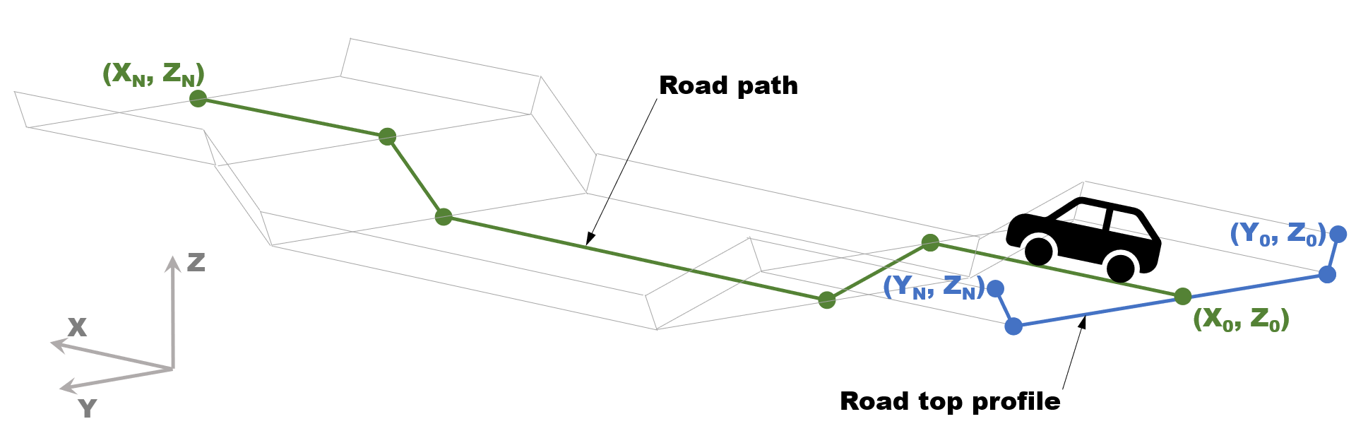
Figure 1. Schematic view of the road generated . Road Path (green line) and the Road Top Profile (blue line). Respective circular markers on the lines represent points in the stencil definition files (pairs of coordinates) which define the lines.
Description
Sliding frame is a part of the “frame suite” feature targeting water wading applications in nanoFluidX. To facilitate the simulation of experiment-like motion of descending into a water filled channel at a reasonable computational cost, sliding frame follows a phase of interest during simulation by moving the computational domain and spawning fluid and road particles as necessary.
There are two modes in which the sliding frame follows the phase of interest. In line lock mode, the sliding frame translates in the X direction only, and in point lock mode, the sliding frame follows both X and Z translational movement of the phase of interest. While the phase of interest may move arbitrarily, the trajectory of the sliding frame is confined to the XZ plane.
The road definition is split into two parts: the road path, which defines the elevation of the road in the XZ plane, and the road top profile, which defines the top side of the road in the YZ plane. It is recommended that both road top profile and road path point coordinates (which define road path and profile lines) are provided in absolute coordinates. Also, you should align the road top profile with the car at the start of the simulation, meaning the road should be close to or touching the tires.
- Is a two column file of the Y Z form.
- Consists of a minimum of two Y Z pairs (two points defining one line segment).
- Has a strictly increasing Y coordinate. Every value in the first column must be bigger than that of the previous line.
- Is a two column file with X coordinate in the first and Z coordinate in the second column.
- Consists of a minimum of two X Z pairs (two points defining one line segment).
- Has a strictly increasing X coordinate.
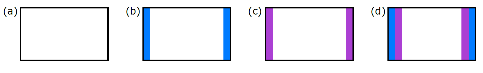
Figure 2. Schematic of inner layers of domain box . Depending on frame_min_bc_overlay and frame_max_bc_overlay. Blue and purple bars represent freeze and sponge layers, respectively. (a) Option 0; (b) Option 1; (c) Option 2; (d) Option 3