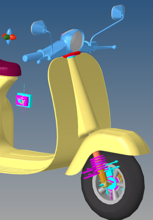
This suspension has a primary barrel tube and a slider tube is placed inside of it,
providing free movement to the later one. It is laden with a spring and shock absorber
inside. In the telescopic suspension, the slider is connected to the yoke of the handle
while the barrel tube or damping unit is connected to the wheel.
Figure 1. Front Telescopic Fork (Classic) with Steering
Model Use
The Front Telescopic Fork Suspension system can be used in two-wheeler full vehicle models.
The default geometry and mass approximate a two wheeler scooter, however the model and data
can be revised to reflect any size two wheeler.
Note:
The wheel body represents the mass and inertia of the tire and
the rim.
The wheel hub body represents the mass and inertia of other rotating bodies such as
a the brake disks or drum. The wheel hub and brake system have no associated graphics.
The wheel and wheel hub parts use the Wheel center location as the center of
gravity.
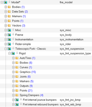
The image below shows the browser view of the systems on a fully populated front suspension
model.
Figure 2. Browser View of Front Telescopic Fork (Classic) Suspension
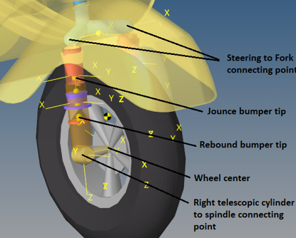
Points
Points locate the joints and bushings that connect the
suspension bodies to one another. The image below shows the principal points for
the Front Telescopic Fork Suspension. Figure 3. Right Side Points – Front Telescopic Fork (Classic) Suspension
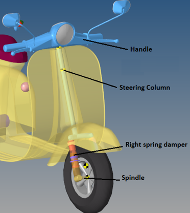
Bodies
The Front Telescopic Fork (Classic) Suspension is comprised of the bodies shown in the
image below: Figure 4. Bodies – Front Telescopic Fork (Classic) Suspension
Bushings and Joints
The table below describes the bodies, bushings, and joints for the Front Telescopic Fork
Suspension:
Label
Type
Body 1
Body 2
Point
Fork Tube to Rod
Translate
Shock Rod
Shock Tube
Shock Upper CG
Rod to Fork Fix
Fixed
Shock Rod
Steering Column
Steering Column Bottom End
Spindle to Fork
Fixed
Spindle
Shock Tube
Wheel Center
Spindle to Wheel
Revolute
Front Wheel
Spindle
Front Wheel CG
Steering REV Joint
Revolute
Handle
Frame
Steering Axis Top
Handle_st_column
Fixed
Handle
Steering Column
Steering Axis Top
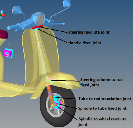
The following image shows the location of the joints and bushings in the
suspension: Figure 5. Joints - Front Telescopic Fork (Classic) Suspension