Flex Tire Tab
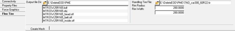
Figure 1.
This tab helps to create mesh files (.bdf/.obj/.off) in the required format that the PM-FlexTire uses (Windows only). Refer to the Pratt Miller software user manual for more details. To generate a mesh, a CAD geometry is needed which is referenced in the .fxt file. The .fxt file can also refer to a regular handling tire file that is needed for a static simulation or a transient simulation where the vehicle is traversing on roads not modeled in EDEM.
Once the mesh is created, the AutoTire can be transferred to EDEM through the MotionView-EDEM coupling interface. See the Bulk Material Interaction topic for additional information.
| Control | Description |
|---|---|
| Create Mesh | Displays the Generate PM-FlexTire files utility to create mesh files for the
tire.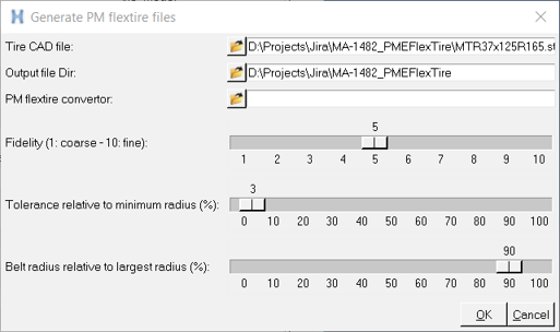 Figure 2.
Note: Refer to the PM-FlexTire User Manual for additional details about the
-tol and -dbelt parameters.
Upon clicking OK, the mesh files are generated and listed in the panel. |
| Output file Dir | Directory to output mesh files that are generated. Defaults to the .fxt file location. The space below displays the bdf/obj/off files if found in this directory. The file names have to match with the *.fxt file name. There are three off files (*_bead.off, *_belt.off, *_inside.off) necessary to transfer the tire to EDEM. The list is automatically populated after the mesh is generated. |
| Handling Tire File | Handling tire file to be used for initial static as well as transient simulation when the tire is not on the road section represented in EDEM. Default – Handling tire file given in the [HANDLING_PROPERTIES] section in the .fxt file. |
| Rim Radius Rim Width |
Tire rim radius and rim width of the tire. Defaults to RIM_RADIUS and RIM_WIDTH parameters in the [BEAD] section in the .fxt file. A “Rim” (cylinder) graphic is created for the AutoTire with these dimensions. The Rim graphic is transferred to EDEM to during the transfer process through the coupling interface. The rim radius and width should match with the actual tire geometry such that it closes the tire carcass. Any gap could have a chance of particles filling the inside of the tire during simulation in EDEM. |