CFD-1400: Hexcore Meshing with Boundary Layer
In this tutorial you will learn how to generate a hexcore mesh with a boundary layer.
Included are the following steps:
- Tria surface meshing
- Boundary layer generation
- Generation of the hexcore mesh, pyramid elements and the tetra mesh
- Preparation of the model for the export
The model file used in this exercise can be found in the es.zip file. Copy the file(s) from this directory to your working directory.
Load the CFD User Profile
-
From the menu bar, click or click the Load User Profile icon,
 , on
the Standard toolbar.
, on
the Standard toolbar.
- Click .
- Click OK.
Open the Model File
-
On the Standard toolbar, click the Open Model
 icon.
icon.
-
Click Open to load the file.
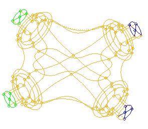
Figure 1.
Generate a Mesh on the Surface
-
Double-click return to close the panels.
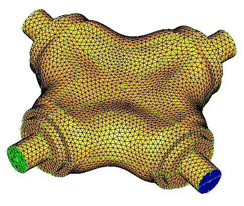
Figure 2.
Mesh the Hex-Core
-
Enter the parameters, as shown in the image below.
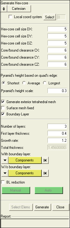
Figure 3. -
Check the Model Browser to see all the new components
created.
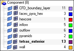
Figure 4. -
While holding the Shift key down, draw a box around
roughly half of the model, and click mask.
This displays the inside of the model.
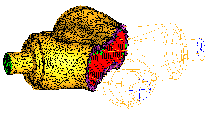
Figure 5.
Prepare the Model for Export
-
Display only the volume elements by clicking the "1" in
the row for 3D elements.
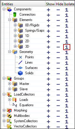
Figure 6.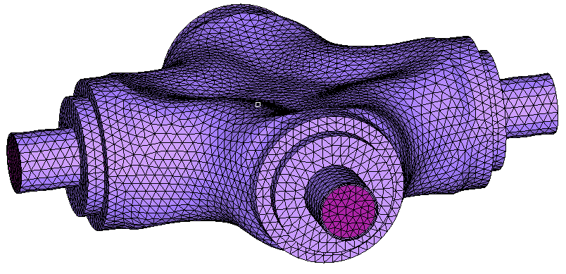
Figure 7. -
In the Mask Browser, set only the 2D elements to
display.
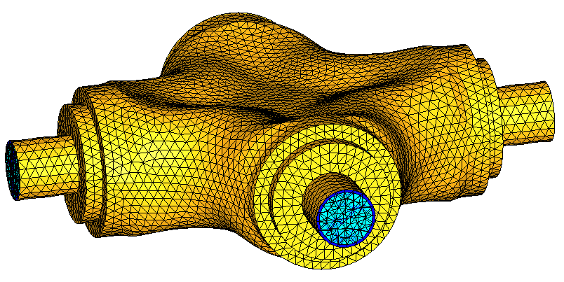
Figure 8. -
Click move.
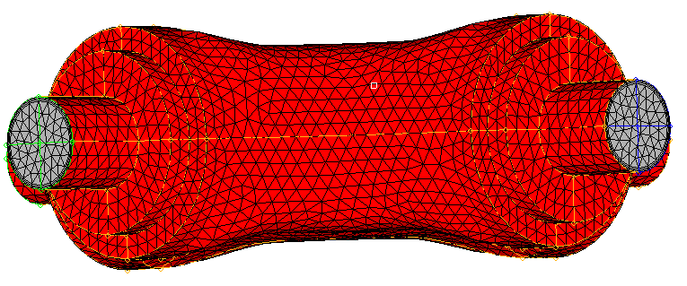
Figure 9.