CFD-1300: Plane 2D Meshing with Boundary Layers
In this tutorial, you will learn to generate 2D boundary layer type meshes with an arbitrary number of layers and thickness distribution in domains defined by edges. You will also generate 2D boundary layer type meshes in areas where the clearance or separation of bounding edges is not enough to accommodate the user specified nominal boundary layer thickness/number or layers.
Load the CFD User Profile
-
From the menu bar, click or click the Load User Profile icon,
 , on
the Standard toolbar.
, on
the Standard toolbar.
- Click .
- Click OK.
Create Nodes
-
Enter the following for the node coordinates: Node 1: 0,
0, 0; Node 2:
0, -30,
0; Node 3: 100,
0, 0; Node 4:
100, -30,
0; Node 5: 300,
0, 0; Node 6:
300, -100,
0; Node 7: 1000,
0, 0; Node 8:
1000, -100,
0.
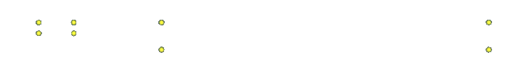
Figure 1. . Nodes are created per the geometry
Create Lines
-
Make your selections and click create.

Figure 2. . Connecting the nodes to form the lines
Create the Surface
-
Click create.
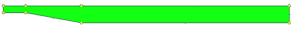
Figure 3. Created Surfaces
Generate a 2D BL Mesh
-
Select Surfaces for generating boundary layer
meshing.

Figure 4. -
Select the lines that do not require 2D BL using the W/o BL (remesh) selector,
since you want the boundary layer to be imprinted on without BL edges.

Figure 5.Note: If 2D BL needs to be collapsed on W/o BL edges, select it using the W/o BL (fixed) selector. -
Set the 2D BL parameters and mesh sizes.
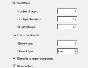
Figure 6.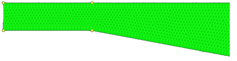
Figure 7.
Summary
In this tutorial, you generated 2D meshes with boundary layers on a complex cross section.
You obtained a high-quality mesh by allowing boundary node insertion and movement. Engineering Solutions automatically cuts back the number of layers when boundary layer collision occurs, thus producing a consistent mesh even in narrow areas. In narrow passages you can also reduce the total boundary layer thickness by starting with a smaller first layer thickness and/or a smaller growth rate.