Manage Configurations
Group common and unique parts/part assemblies together in part sets, and organize parts and part sets that are unique to a configuration.
In the traditional model build and assembly workflow, subsystems that contain multiple variants are stored in multiple HyperMesh binary files. This complicates the model build and update process as part updates and revisions will need to be performed on each binary file.
- Left-hand drive (LHD)
- Right-hand drive (RHD)
- Fixed roof (Fixed)
- Panoramic roof (Pano)
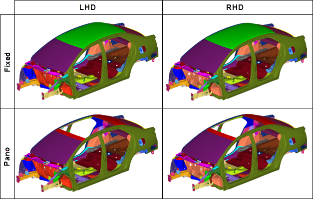
Figure 1.
All common and unique parts that appear in all configurations for a given subsystem are stored in a single HyperMesh binary file, known as a Layered Model. In a Layered Model, common parts are active in all configurations. Unique parts are active only in a specific configuration. You must deactivate unique parts not appearing in a configuration.
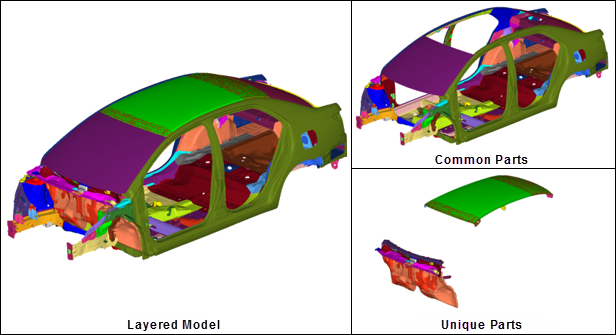
Figure 2.
About Part Sets and Configurations
Part sets group common or unique parts, and configurations organize parts and part sets that are mutually exclusive to a configuration.
Example: Configuration Management Workflow
Configuration management workflow for a Dash and Cowl subsystem.
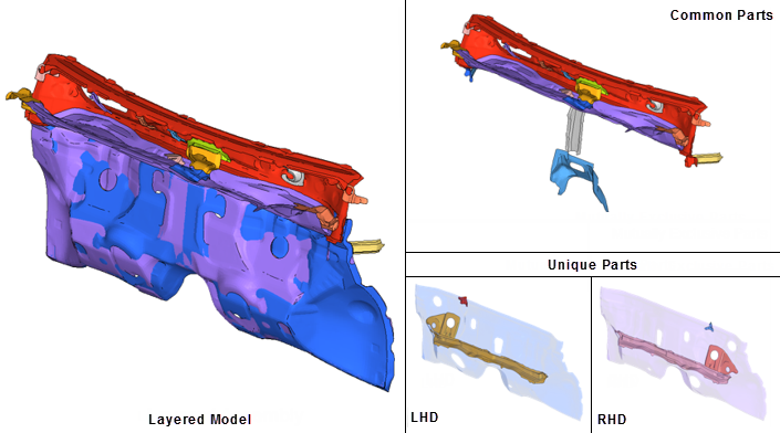
Figure 3.
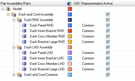
Figure 4.
- Clear the Active column for the following individual, unique parts that
belong to the RHD configuration.
- Dash Panel RHD
- Dash Bracket Large RHD
- Dash Inner Bracket RHD
- Dash Cross Member RHD
- If all unique parts are nested in a single part assembly, clear the Active column for Dash RHD Assembly.
- If all parts and part sets that are unique are organized in a configuration, enable the LHD configuration’s associated checkbox in the Active column of the Configuration view.
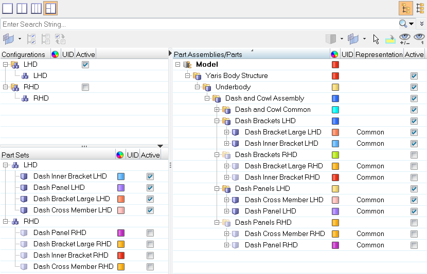
Figure 5.
Create Part Sets
Create Configurations
- Open the Part Browser.
- In the Configuration view, right-click and select from the context menu.
- From the Part and/or Part Set views, click-and-drag parts, part assemblies, and part sets that are unique to a configuration onto the configuration.
Remove Contents of Part Sets and Configurations
- Right-click on the entity and select Remove from the context menu.
- Drag the entity into the white space of the respective browser view.
Activate/Deactivate Configurations
Control the display and export state of parts and part assemblies by changing the active/inactive state of configurations.
Entities set to inactive are still visible in the Part Browser. Deactivated components will not be visible in the Model Browser, Display panel, and panel entity collectors.
Create and Organize Part Sets from PDM Variants
- In the Part Browser, Part Set view, right-click on a part set entity (if available) or in the white space and select Create Variants from the context menu.
- In the Confirm Create Variants dialog, click Yes.
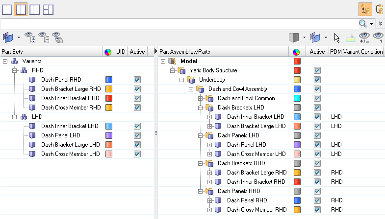
Figure 6.
PDM Variant Conditions
PDM Variant Conditions are utilized in PDM systems, such as Teamcenter, to mark similar parts in BOMs that may contain multiple variants, such as an automotive BIW.
- PDM Variant Condition
- If non-empty, the part is used as a variant in one or more part configurations.
- PDM Variant Scope
- Along with the Variant Condition attribute, it describes which part configurations the part belongs to as a variant.
Part sets are created per PDM Variant Condition attribute found in the global part assembly/part hierarchy. The operation can be invoked at model, part assembly, or part level.
You can organize part sets from PDM Variants in any view of the Part Browser.