Pedestrian Impact
The Pedestrian Impact tool automates the vehicle marking, impactors positioning and the export of solver decks with minimal input, therefore reducing the full process lead time.
The tool conforms to the pedestrian safety regulations EuroNCAP, GTR/UN-R127, GB/T/CNCAP 2018, EuroNCAP 2022/2023(bicyclist) and CNCAP 2021(bicyclist).
From the menu bar, click .
- The vehicle is positioned with its centerline on Y=0 plane and oriented in the -X global direction.
- The initial position of the impactor is in the +X global direction and CoG at global (0;0;0) coordinates.
- The master files for each of the impact load cases need to be prepared in advance with the necessary include files, except for the impactor include.
The Pedestrian Impact tool automatically exports the master file for each of the selected impact points and automatically adds the impactor include file and the transformation cards.
Vehicle Marking
-
- Regulation: Select one of the supported regulations.
- Impactor: Select one of the following:
- Headform: Child and adult head impact
- Legform: lower-leg and upper-leg impact
- All: Perform all impact load cases
- Parts selection
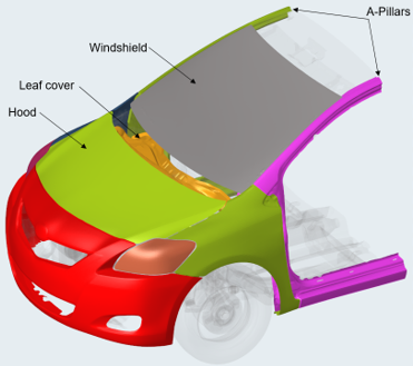
Figure 1. Vehicle Outer Surfaces- Bumper Beam: If leg form impact points must be created, select the Bumper Beam
components.
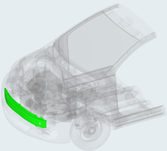
Figure 2. Bumper Beam Components
- Bumper Beam: If leg form impact points must be created, select the Bumper Beam
components.
- Vehicle Inclination: For the marking process, you must define the ground level, which
gives the reference level of the construction lines. Below are the different options
that are available.
- Ground Type
- Flat: The ground is flat with normal in Z direction. You can specify the Z distance manually or select a node on the graphic.
- Inclined: The ground level can be specified by selecting two nodes or
providing coordinates manually for Base node and Inclination node. The rotation
of the ground is then automatically calculated based on the coordinates of the
nodes.
- Inclination Type: Base Node: The rotation is calculated around the
provided base node.
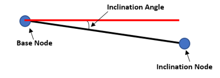
Figure 3. Inclination Type = Base Node - Inclination Type: Forward Rotation: The rotation point position is
automatically defined on the front of the vehicle.
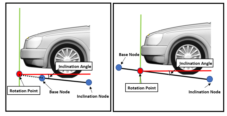
Figure 4. Inclination Type = Forward Rotation
- Inclination Type: Base Node: The rotation is calculated around the
provided base node.
Regulation options: Pedestrian marking parameters can be customized, saved as a .txt file and reused.
Click Mark to create pedestrian marking.
- Ground Type
- Created Marking Entities: The Pedestrian Impact tool automatically generates:
- Marked entities(EuroNCAP)
- Wrap Around Distances lines (WADs)
- Left and Right Bonnet Side Reference lines (LSR and RSR)
- Bonnet Leading Edge (BLE)
- Bonnet Rear Reference Line (BRRL)
- Upper Bumper Reference line (UBR)
- Lower Bumper Reference line (LBR)
- Internal Bumper Reference line (IBR)
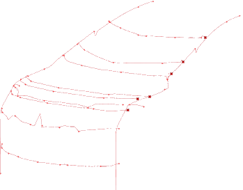
Figure 5. Marked Entities
- Construction lines and spheres used to create the Test Area Lines:
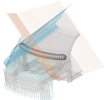
Figure 6. Construction Lines and Spheres - Front and gap tape components that are used to close the openings at the front of
the vehicle and in the gap between the windshield and hood:
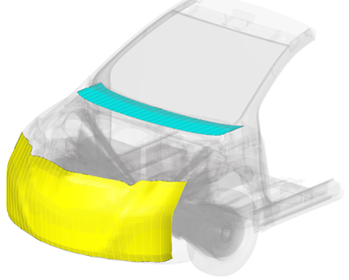
Figure 7. Front Tape and Gap Tape - Impact points for the selected load cases (Headform, Upper-Leg, Lower-Leg). The
impact points are stored as design point entities in the Model Browser. Each impact point has its own graphic and name defined
as per the regulation protocols.
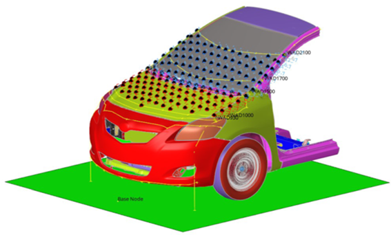
Figure 8. Front Tape and Gap Tape
- Marked entities(EuroNCAP)
- Export as CAD: Pedestrian marking (geometric lines, surface and impact locations) can be saved as an .iges file.
- Save: Save as a .hm file.
- Delete Mark: Delete all of the pedestrian marking.Note: For the GTR/UN-R127 protocol, an additional section is exposed in the tool to allow the generation of targets points based on user-defined spacing.
EuroNCAP Windshield Periphery Detection
- Select Frik lines defining front line, top line, left line and the bottom line as the geometric line.
- Click Identify to identify the default green zone per EuroNCAP.
- Click Reset to reset the identified green zone.
Show/Hide
Switch on/off pedestrian marked entities.
Hard Parts
The Hard Parts tab allows you to plot a distance contour distribution of Hard parts on the Vehicle outer and determine package space detection.
Hard Parts Contour: Identify critical areas of impact for the head and leg.
Vehicle Outer: Select Vehicle Outer parts.
Hard Parts: Select hard parts to consider for distance contour.
- Adult Child Headform
- Upper Leg
- Lower Leg
Max length: Distance value to be considered for contouring.
Impactor Angle: The angle value that will be considered at which computed distance of Hard parts will be projected to Vehicle Outer.
Project direction: For Headform projection direction this can be set to Up (on hood) or Front (on bumper).
Contour: Plot the distance distribution as contour.
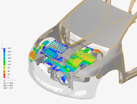
Figure 9. Headform Hard Parts Contour
Clear: Clear the created contour.
Offset Zones/Package space detection: Using offset zones, you can identify critical areas of impact for the head and leg.
- Adult Headform
- Child Headform
- Upper Leg
- Lower Leg
Offset Zone distance: Distance values for each of the colored zones.
- Impactor File Type: Select either Impactor File or Impactor Skin File.
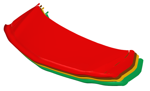
Figure 10. EuroNCAP Child Headform Zone Offsets
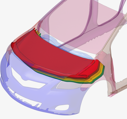
Figure 11. Child Headform Zone Offsets Transperancy
Hide: Transparency is reversed for all parts.
Delete All: Delete all of the created offset zones.
Refinement
- Vehicle Outer: Select Vehicle Outer parts.
- Impactor: Select Headform, Lower Legform
or Manual Creation.
- Headform:
- Array type: Types of refinement selection.
- One Point (Circular)
- Two Point (Line)
- Three Point (Triangular)
- Three Point (Rectangular)
- Along One Line
- Between Two Lines
- Clearance: Distance value to be considered for local refinement.
- Radius: If Array type = One Point (Circular), define the distance value for the circle radius.
- Points to create: Number of local refinement points to be created.
- Node/design point selection is for refinement.
- Array type: Types of refinement selection.
- Headform:
- Create: Generate refinement points.
- Delete All: Delete all of the local refinement points.
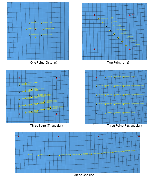
Figure 12. - Lower Legform:
- Array type: Types of refinement selection. Select Between Points or Along UBRL.
- # Points to create: The number of local refinement points to be created.
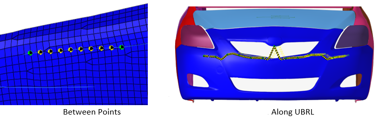
Figure 13. - Node/design point selection is for refinement.
- Manual Creation:
- Array type: Types of refinement selection.
- Node/Coordinate/CSV file selection.
Positioning
The Pedestrian Impact tool automatically exports the master file for each of the selected impact points and automatically adds the impactor include file and the transformation cards.
- Units: Select supported units for Upper Leg velocity.
- Gap: Gap to be considered between the positioned impactor and the vehicle.
- Vehicle Outer: Select Vehicle Outer parts to be considered for impactor positioning.
- Wiper Blades: Select wiper blade parts to be considered for impactor positioning.
- Deployed Hood: Select deployed hood parts to be considered for impactor positioning.
- Impact Points table: Access and manipulate created impact points with multiple
functions.
- Selection of impact points: You can use shortcuts, such as Ctrl+A (select all points) and Ctrl+left click to select the desired point.
- Search bar: Search impact points based on ID, name and structural property.
- You can sort each column by clicking on the column titles.
- You can configure the impact point table based on impact point structural properties by right-clicking on column titles.
- Pedestrian Export Setting: You can apply multiple impactor positioning and create
files ready to be solved. If activated, you can control the positioned impactor file
path definition, and the include file path of the positioned impactor will be converted
from absolute to relative file path. All of the include files referred to in the master
file will be copied back to the analysis folder. The target .csv
file for the selected impact points will be exported.
- Impactor File Type: Select all of the impactor files. If Impactor Skin File is
selected, you need to select an input file that contains impactor outer skins.
You must create an impactor skin input file with listed part names. For lower leg you can select from the drop-down menu.
- Impactor File Type: Select all of the impactor files. If Impactor Skin File is
selected, you need to select an input file that contains impactor outer skins.
- Preview: Preview selected points at Impact Points table.
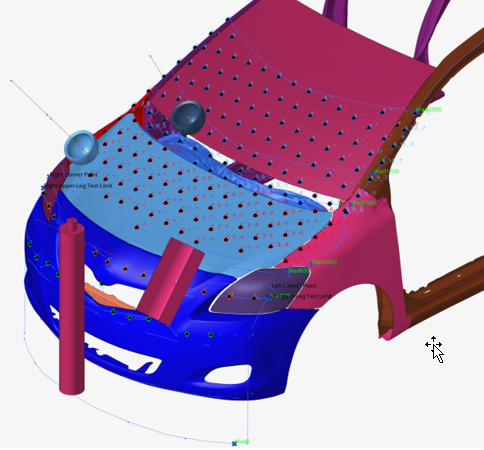
Figure 14. All Four Impactors Previewed - Cleanup: Delete all positioned impactor skins for preview.
- Export filters
- All: Position and export all impact points.
- Selected: Position and export to only selected points at Impact Points table.
- Adult Headform: Position and export all Adult Headform points.
- Child Headform: Position and export all Child Headform points.
- Upper Leg: Position and export all Upper Leg points.
- Lower Leg: Position and export all Lower Leg points.
Export Options
- LS-DYNA
- The impactor include file is defined as an *INCLUDE_TRANSFORM and the
*DEFINE_TRANSFORM cards are automatically generated and assigned to the
*INCLUDE_TRANSFORM.
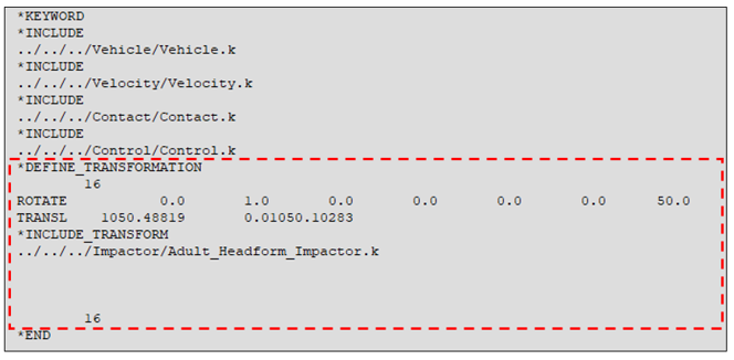
Figure 15. Example Master Files for LS-DYNA - Radioss
- The impactor include file is defined in a //SUBMODEL and the /TRANSFORM cards are automatically generated with reference to the impactor sub model.
-
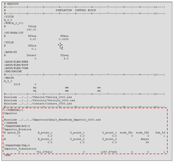
Figure 16. Example Master Files for Radioss
- Select the master file for Adult Headform.
- Select the master file for Child Headform.
- Select the master file for Upper Leg.
- Select the master file for Lower Leg.
- Preview Deck: Opens a text editor for previewing and editing the corresponding master file.
- Select the output directory.
- Export: Position and export solver decks.