Spot Realization
Overview of the spot connector realization process and methods.
Spot Realization Process
Overview of the spot realization process.
- Select the realization type.
- mesh independent
- Use for realizations that do not need a node connection, and the connection is primarily defined via a solver-specific card, such as CWELDs for Nastran.
- mesh dependent
- Use for all other cases.
- If mesh dependent is selected, you must decided whether or not to adjust the
mesh or the realization.
- Adjust mesh
- Projection is done in a perpendicular way, and the mesh has to be adapted to the projection points.
- Adjust realizations
- The mesh will not be modified, at the expense of non-normal or incomplete realizations. Many realization types are defined with head elements attached to body elements. In the case of these realization types, the head elements realize the connection without modifying the mesh. Then the body element is still created in a normal direction.
- Select a method for performing adjustments.
- Adjust mesh
- Sub-options include: quad transition and remesh.
- Adjust realizations
- Sub-options include: find nearest nodes, project and find nodes, and ensure projection.
- Choose whether or not the imprint should be skipped for quad transition.
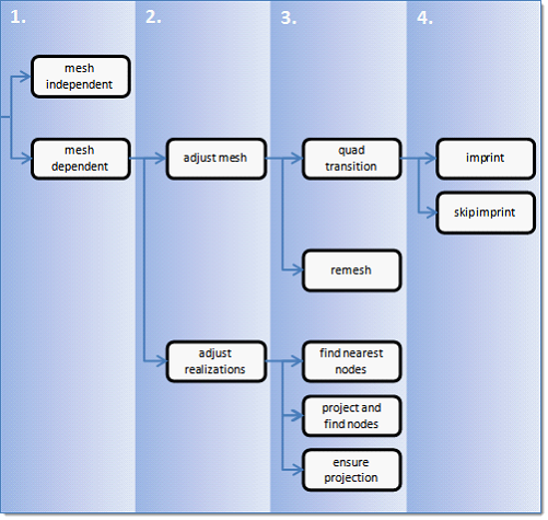
Figure 1. Spot Realization Process
Spot Realization Methods
Overview of the different options for spot realization methods.
Mesh Independent
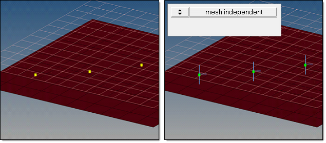
Figure 2. Mesh Independent
Mesh Dependent – Adjust Mesh – Quad Transition – Imprint
Figure 3. Mesh Dependent, Adjust Mesh, Quad Transition, Imprint
- Quad Transition
- The quad transition option creates perfectly shaped quad elements around the
projection points. By default, the quad size is determined by the average mesh size.
Alternatively, you can specify a specific quad size in the quad size field.
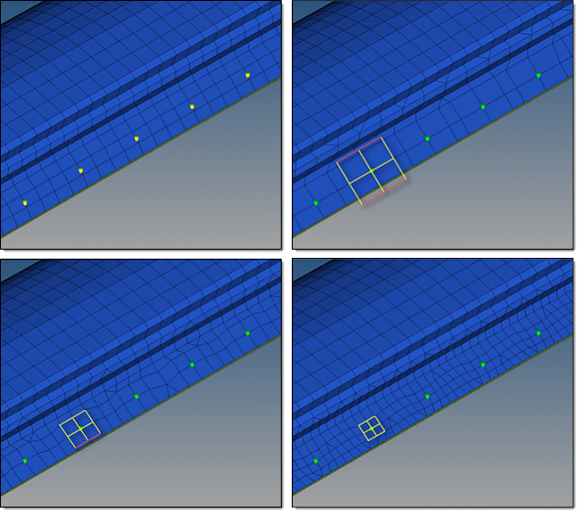
Figure 4. Connectors Realized with Quad Transition using Different Quad Pattern Sizes. The top, left image illustrates the initial model situation. The remaining images illustrate connectors that have been realized with quad transition using different quad pattern sizes: average, coarse, small. The regular quad pattern size is highlighted and the red lines illustrate which nodes have been snapped to a relevant feature or free edge. -
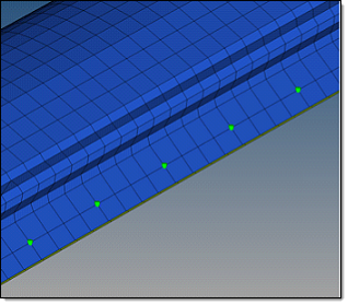
Figure 5. Connector Realized with Quad Transition using Adequate Quad Pattern - In curved regions the inner and outer lengths of the element edges differ.
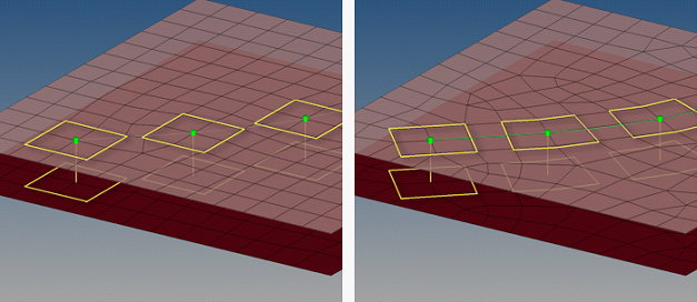
Figure 6. Split to Points Example - Imprint
- When creating mesh-dependent realizations with quad transitions, the quad transition meshes can overlap and disturb each other if more than one set of connectors is created too close to each other. Select the imprint option to reconcile such transitions with each other and modify the underlying mesh to match the results, creating a final result that is seamless and properly meshed.
Mesh dependent – Adjust Mesh – Quad Transition – Skip Imprint
- Quad Transition
- The quad transition option creates perfectly shaped quad elements around the
projection points. By default, the quad size is determined by the average mesh size.
Alternatively, you can specify a specific quad size in the quad size field.
Figure 7. Connector Realized with Quad Transition using Adequate Quad Pattern. The top, left image illustrates the initial model situation. The remaining images illustrate connectors that have been realized with quad transition using different quad pattern sizes: average, coarse, small. The regular quad pattern size is highlighted and the red lines illustrate which nodes have been snapped to a relevant feature or free edge. - By default, snapping is allowed by a distance of one third of the quad pattern
element size. In the case of a predefined quad pattern element size of 10.0, the outer
nodes can snap to features in a distance of 3.3. The algorithm also tries to snap all
three nodes of a quad pattern or none.
Figure 8. Connector Realized with Quad Transition using Adequate Quad Pattern - In curved regions the inner and outer lengths of the element edges differ.
Figure 9. Split to Points Example - Skip Imprint
- The skip imprint option prevents the last step of quad transition from being performed. The component ^conn_imprint is created instead, which contains the element pattern. These elements can be modified and manually imprinted later using the Connector Imprint panel.
- Skip imprint allows you to realize such mesh-dependent realizations in very complex
areas of the model where the automatic imprint fails because of issues such as
conflicting spots.
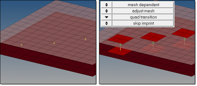
Figure 10. Skip Imprint
Mesh Dependent – Adjust Mesh – Remesh
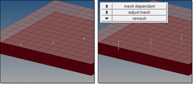
Figure 11. Mesh Dependent, Adjust Mesh, Remesh
Mesh Dependent – Adjust Realization – Find Nearest Nodes
The find nearest nodes option searches for the nearest nodes within the given tolerance only, making it possible to connect t-joints and similar areas. This option is also very useful in situations where the connectors are not positioned perfectly. The realizations are allowed to be non-normal.

Figure 12. Mesh Dependent, Adjust Realization, Find Nearest Nodes
Mesh Dependent – Adjust Realization – Project and Find Nodes
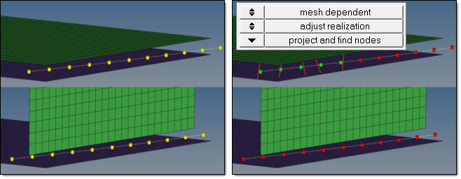
Figure 13. Failed Realization

Figure 14. Non-Normal Projection
Mesh Dependent – Adjust Realization – Ensure Projection
When the ensure projection option is selected, the minimum condition for the realization is a possible projection. The realization will be performed in the direction from one projection point to the next. If the projection point is coincident with a shell node they will be equivalenced.
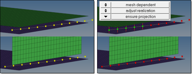
Figure 15. Ensure Projection
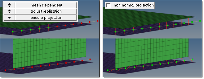
Figure 16. Ensure Projection with Non-Normal Projection