Panel Composite Specialization
Panel Composite Structural Property
In addition to the common data names for panels, Panel_composite config has another data name, property, which should point to a solver composite property. Properties are not meant to vary across elements inside the panel using this attribute. Using the Absorb FE option during Auto DDP, the panel’s central element is used as a reference. A copy of it's property will be referred to by structural property (PCOMP and PCOMPG).
- Query structural property and retrieve property/materials from it.
- If no property is assigned to the structural property, the query is done at the element level.
It is possible to support methods that evaluate on element basis even using panel config for design point. Properties and materials can either be element based or common overall the design point if a property is assigned to structural property.
First Ply Failure Method
Panel_composite config comes with a set of composite laminates first ply failure criteria. All of the failure criteria is bundled in a single certification method called First_Ply_Failure. This method internally invokes ESACOMP engine.
Panel_composite config evaluates failure criteria per element basis. If the structural property assigned to a given design point refers to a user-defined property (PCOMP or PCOMPG) then all attributes required by the method will be queried from this property. Otherwise, it will go directly per element’s property (supports PCOMP, PCOMPG, PCOMPP properties and MAT1, MAT8 cards). All composite stresses are recalculated from shell element forces and moments based on the reference laminate property used. It is required that result files contain shell element resultant forces and moments.
Math
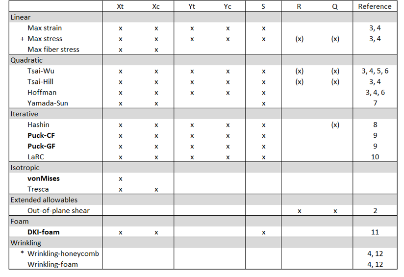
Figure 1.
+ Max stress for isotropic material requires Xt, Xc and S and considers out-of-plane shear.
- R= Transverse_Shear_Allowable_S13
- Q= Transverse_Shear_Allowable_S23
- *E3
The bolded design criteria automatically considers out-of-plane shear stresses.
If R and Q (for MAT8) are defined, traditional in-plane criteria will also consider the out-of-plane shear.
Terminology
Reserve factor is a measure of margin to the onset of failure. The effective load multiplied with the reserve factor gives the design margin. Reserve factor values greater than one indicate positive design margin and values less than one indicate negative design margin. The values of reserve factors are always greater than zero. The term factor of safety is used with the reserve factor/inverse reserve factor/failure index. For linear criteria (max strain, max stress and max fiber stress) it equals to the value of the failure function f. Margin of Safety = Reserve Factor – 1.
Activate Failure Theories
Once the First_Ply_Failure method is added to a design point set, you can edit it from the browser. First, you can select the result level (Element|Layer|Recovery plane), then the type of margin to evaluate.
The failure theories that are available are grouped in categories in the Entity Editor. You will activate methods of interest by providing materials to use for failure evaluation. All failure theories require allowable to be set directly in the referred material entities. Whenever these allowables are meant to be available directly as a solver card (MAT1/MAT8 attributes) they will be queried from the material card. Extra allowables, not available from the solver deck, are automatically created as metadata attached to referenced material entity in HyperMesh. Metadata can be edited in each material Entity Editor. If a metadata already exists, it will not be overridden. Metadata is stored in the HyperMesh binary file along with the model.