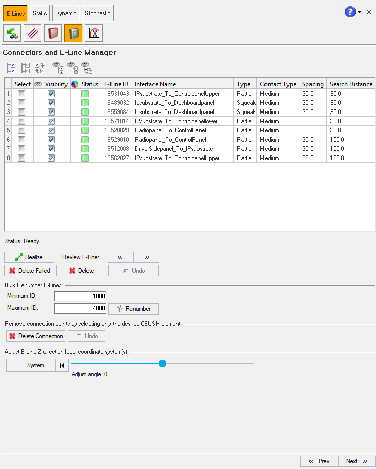
After creation of E-Lines connectors using the Manual and/or Auto methods, all the
evaluation lines with connector locations and other related parameters will be listed in
Review E-lines panel. Below is the image of Review
E-Lines panel. Figure 1.
The E-line data is tabulated in the following format:
Select
Options to select the required E-Line
Select All
Unselect All
Reverse Selection
Visibility
Check box option to turn on or off the visibility of the
E-Line
Show All
Hide All
Reverse Visibility
Status
Contains the Elines realization status
Yellow - unrealized Elines
Green - realized Elines
Red - failed to realize ELines
E-Line ID
Contains the information for interface number along with the
number of connectors for respective lines
Interface Name
Contains the information for the gap/interface name
Type
Contains the information for the type of ELine
Contact Type
Contains the information for contact type.This information is
defined based on Youngs' modulus values
Spacing
Value for the spacing between two adjacent connectors
Search Distance
Value for search/gap tolerance between the selected master slave
component
Review ELines panel allows you to perform following actions:
Delete Failed - to delete any failed lines in the session
Delete - to delete only the selected Eline from the table
Visibility Navigation - to view the successfully realized E-Line.
This option isolates selected interface, and the components in graphics
area
Navigation buttons are provided to cycle through the list of E-Lines
Realize - to realize Elines to create connecters and related properties
You can realize single or multiple E-lines from the table
Also, you can edit and update following parameters:
Interface Name
Line Type
Contact Type
Spacing
Search Distance
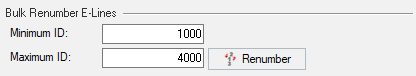
Bulk Renumber E-Lines - you can renumber the E-Lines from the list based on a
range:
Minimum ID
Maximum ID
Delete Connection - you can delete realized connection points from an
ELine
This will update the interface number based on the number of connections
deleted
Undo - to undo/revoke Delete Connection
operation for the immediate previous step
ELine realization
An ELine is said to be realized, only when the below mentioned processes occurs and
the respective components are created and listed in Model
browser tab. For the below mentioned process, standard
HyperMesh options are utilized, but automated with SnRD
options. Once you clicks Realize Selected option,
RBE3 elements are created on master and slave
component and assigned with an unique ID. The numbering of RBE is based on
the interface number.
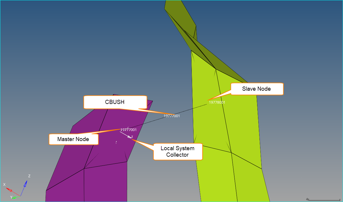
Slave component CBUSH nodes are assigned IDs with 1000 incremented
to that of Master Component CBUSH nodes, I.e if CBUSH master node is
510001, CBUSH slave node will be
511001
CBUSH elements are created between the
RBE3 spiders created between the master and slave
component. CBUSH ID is same as Master RBE ID.
For a Rattle line, a
CBUSH_Rattle property is created, with
K values zero in all
directions.
For a Squeak line, a
CBUSH_Squeak property is created, with
K values zero for
K1, K2, K4, K5, K6.
K3 is assigned with 1000
[N/mm] value.This is a default value that can be
modified by the analyst depending on the application. This is a
constraint Z direction motion between master
and slave for squeak line scenario.
A local system collector is created at the master RBE node, where
Z direction defines the direction of the relative
displacement. The orientation is based on gap
direction defined while creating the connectors.
Normal to master
Inplane to master
Initial Interface number is also updated with the
number of connectors realized appended at the end. For example, if a
interface number 510000 is realized, and
24 connectors are created along the interface, then the
final interface number will be 510024.
Figure 2.
Bulk Renumber E-Line
With the help of Bulk Renumber E-Lines option, you can
renumber existing evaluation lines with a range from minimum to maximum ID. After
renumbering, the corresponding E-Lines, RBEs and CBUSH elements are assigned with
the new range of minimum and maximum values. Figure 3.
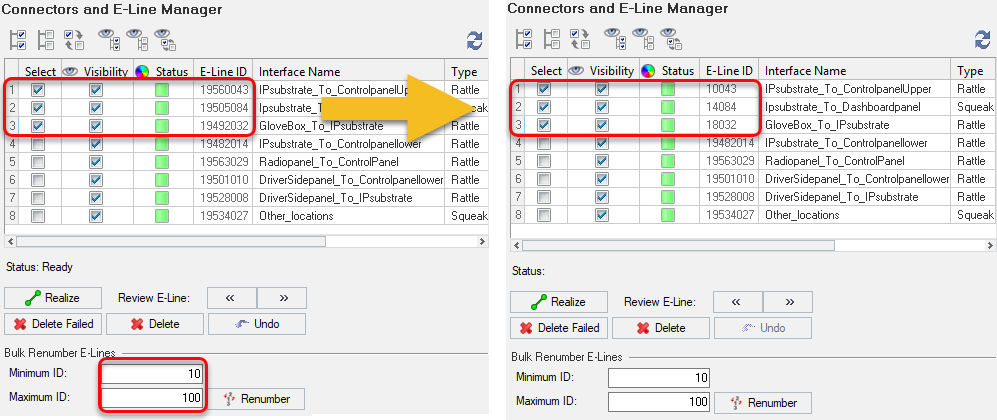
E-lines renumbering follows the below principle
-
Minimum ID input value * 1000 + n = Renumbered Master ID
Renumbered Master ID + 1000 + n = Renumbered Slave ID
where n is the number of E points in the line.
Below is an example for renumbering of existing E-Lines.
From the E-Lines list, select the required lines for renumbering.


 Yellow - unrealized Elines
 Green - realized Elines
 Red - failed to realize ELines