BasicFEA

Midsurface panel

Midsurface panel

Previous topic Next topic Expand/collapse all hidden text  

Midsurface panel

Previous topic Next topic JavaScript is required for expanding text JavaScript is required for the print function  

Use the Midsurface panel to extract the midsurface representation of a solid part or to generate a finite element shell representation of a solid geometry. This panel can be used to extract the midsurface of sheet metal stampings, molded plastic parts with ribs, and other parts that have thickness clearly smaller than width and length.


Panel Usage


The Midsurface panel consists of several tools, which can be selected using the switch on the left-hand side of the panel. Each tool consists of several different subpanels.


Subpanels and Input


The Midsurface panel contains the following tools:

hmtoggle_plus1greyAuto Midsurface Tool

Midsurfaces can be extracted and modified using the auto midsurface tool.

The auto midsurface tool contains the following subpanels:

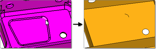
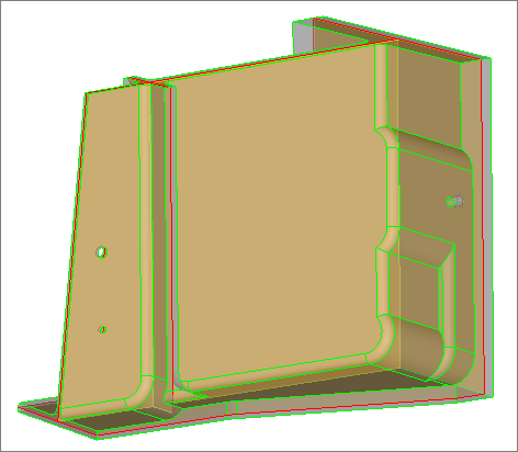
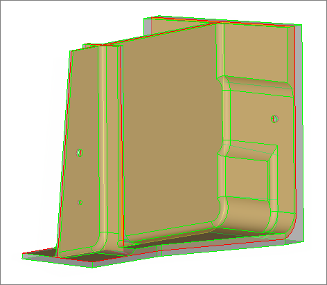
Use the Auto Midsurface subpanel to extract, in one step, the midsurface of a more complicated group of surfaces that represent a solid part.


Panel Inputs

Input

Action

entity selector

Select the surfaces or solids from which you wish to extract midsurfaces.

closed solid / incomplete solid

closed solid

Select a single surface of the solid geometry and click extract. The enclosed volume the selected surface belongs to is automatically determined, and the midsurface is extracted from it.

incomplete solid

Enables additional options for selecting and orienting the surfaces defining the body to extract.

select connected surfaces

Once you select a single surface, all of the attached surfaces are automatically selected.

Only available when incomplete solid is selected.

outbound normals (red)

Indicates that the normals of the selected volume point outside the enclosed volume. Clear this checkbox when the normals point inside the enclosed volume.

The normals of the selected surfaces are displayed as soon as your selection is completed.

Only available when incomplete solid is selected.

color display normals / vector display normals

Determines how the normal direction of the selected surfaces is displayed: as vectors or in colors (color display is recommended).

When normals are consistent, color display normals colors the outer surfaces of the model red or blue, but never a mixture of both. For most models, normals are automatically oriented consistently.

fix normals / reverse normals

Reorients surfaces that do not have a consistent normal direction.

If surface normals are inconsistent, reset your surface selection and select the surfaces for which normals need to be adjusted, then click reverse normals.

To automatically fix the normals of all the surfaces in the selection, click fix normals.

The consistent orientation of normals (either all normals pointing outside the part, or all pointing inside the part) is crucial for the success of the midsurface extraction.

extract

Extracts the midsurface.


Use the extraction options subpanel to define midsurface extraction settings.


Panel Inputs

Option

Description

offset + planes + sweeps / offset + planes / offset / skin offset

offset + planes + sweeps uses a midsurfacing algorithm to identify the places where a piece of plane or a piece of a sweep surface can be used as a middle surface. A middle surface is constructed at the remaining places in the model, for example the places where planar or sweep surface pieces cannot be used as a middle surface, by the same algorithm as in offset via the offset of the model's sides.

midsurface_offset_planes_sweeps

offset + planes uses a midsurfacing algorithm to identify the places in the model where a piece of plane can be used as a middle surface. At the remaining places in the model, for example the places where planar pieces cannot be used as a middle surface, the same algorithm as in offset is used to construct the middle surface via the offset of the model's sides.

midsurface_offset_planes

offset creates pieces of the middle surface by offsetting the model's side surfaces towards the middle. This is the traditional approach for midsurfacing in BasicFEA.

midsurface_offset

skin offset generates a midsurface by duplicating and offsetting the inner skin surfaces (those with the smallest area) and assigning them a constant thickness.

The parts you provide to the algorithm must be relevant. T-connections, varying thickness, or internal ribs/features/creases are not relevant.

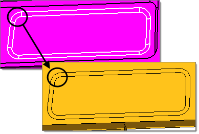
align steps/keep step jumps

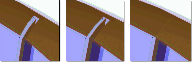
In the case of a part that has different "steps" of thickness, such as a flat sheet that is twice as thick at one end as the other, but uses an abrupt step-like change in thickness instead of a constant slope or curve, align steps aligns midsurfaces whereas keep step jump produces steps between the various midsurfaces as in the original model.

When align steps is selected, this option and all of its sub options (user mid position/auto mid position, and the value for the user-specified mid-position) will only be executed during midsurfacing when there is a single surface on one side, and several surfaces located at different distances (thus forming steps) in front of the single surface.

align_steps_valid_steps

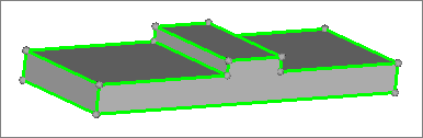
Example of valid steps, where steps are in front of a single surface.

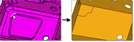
If steps are not in front of a single surface, but instead are in front of several surfaces, then steps will not be recognized as something that can be aligned during midsurfacing.

align_steps_invalid_steps

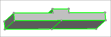
Example of invalid steps, where steps are in front of multiple surfaces.

If steps appear on both sides of the expected midsurface, then align steps will be applied, but it is not guaranteed the steps will be aligned during midsurfacing.

Only available when you select offset.

auto mid position / user mid position

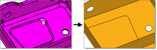
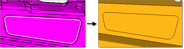
auto mid position, creates a midsurface parallel to the largest side of the volume. This midsurface includes "offset" data to represent the changes in distance between the midsurface and the smaller faces at each "step".

midsurface_SolidWithSteps

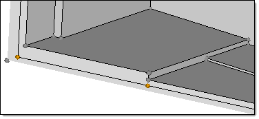
The midsurface (with orange nodes) is parallel to the larger face of the solid plate

user mid position enables you to define the offset of the midsurface, using a value from 0 to 1, in order to specify the offset from the largest side of the volume.

Only available when you select offset and align steps.

allow rerun

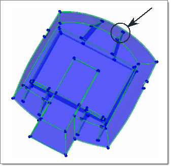
Provides a shortcut to the edit collapsed lines subpanel, from which you can enable visualization settings to display point associations on the midsurface after extraction, and create and edit collapsed lines.

When extracting a new midsurface, the midsurface is generated using the collapsed lines that were automatically found during the initial midsurface extraction and the lines that you manually collapsed.

If allow rerun is disabled or the allow rerun switch is set to no rerun or prepare for rerun, then the lines that you manually collapsed will not be used when a new midsurface is extracted.

use base surfaces

Provides a shortcut to the edit base surfaces subpanel, from which you can specify a distance from the base surfaces of multiple solids, that you wish to treat as if they were continuous, in order to generate separate-but-aligned midsurfaces during extraction.

If use base surfaces is disabled, new midsurfaces will not be generated at the specified distance from the selected base surfaces. The setup of the base surfaces that you modified will be retained for future use as long as you do not delete them.

thickness bounds/
no thickness bounds

Determine whether or not to specify thickness bounds for the plates in the part.

thickness bounds enables you to specify a minimum and maximum thickness of the plates in the part. Middle surfaces are only created for plates with a thickness that falls into the specified range. Thickness bounds can improve the robustness of the results and speed up middle surface creation; however, you must be sure that you do not cut off some plates by selecting thickness limits that are too narrow.
no thickness bounds enables you to specify a max thickness ratio for midsurface extraction. This is the highest acceptable ratio of the thickest plate’s thickness to that of the thinnest plate. Plates whose thickness is greater than this value multiplied by the thinnest plate’s thickness is ignored. Using too small of a value can cause incorrect midsurface extraction. However, larger ratios take more time to process.

max R/T ratio

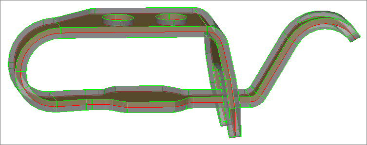
This ratio is taken into account on T-, X- and more complex connections only, as in the image below. On a curve without a T-connection (like on the right side on the picture) it does not apply.

midsurface_RT

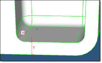
If R/T is greater than the specified value, then this location will not be recognized as a junction and will be considered as a solid piece.  If T is different on different sides on the junction (as in the above picture), then the maximum T is used.

Since in many cases the fillet is not an exact cylinder and has a variable curvature, or the fillet cross-section is not orthogonal to the fillet axes, in reality the length on the curve at the fillet is taken and R is recalculated from this length as if it were an arc of a circle.

Previously, this parameter was only used internally and was set at a value of 2.0.

thickness based stitch tol

Performs the final stitching of midsurfaces with a locally-defined tolerance of 1/5 of the local thickness (which was the default in the previous HM versions).

If unchecked, the global cleanup tol specified in the Options panel is used for stitching. This method is recommended when an extensive manual edit of the auto midsurfacing result is expected, because stitching comparatively distant midsurfaces may misrepresent the geometry of the model and affect following operations on geometry.

extract by component/cross components

This option is useful when you are trying to extract the midsurface of multiple parts in a single step.

If each part is contained in its own component, select extract by component to extract the midsurface of one component at a time.

If your model contains a single part organized in multiple components, select cross components.

result in Middle Surface comp/result in current comp / sorted results

Determines where to organize midsurfaces upon creation.

result in Middle Surface comp organizes midsurfaces in the Middle Surface component (Recommended).
result in current comp organizes midsurfaces in the current component.
sorted results performs midsurface sorting immediately after extraction.

sort Middle Surface comp into

Specifies how to sort the middle surfaces immediately following extraction.

<~[o]riginal name> comp creates new components by removing the first letter of the original component name and replacing it with a ~ and sorts the midsurfaces accordingly.  For example, my_comp -> ~y_comp.
<Midsurface #nn> comp creates components with the name Midsurface #, where # increases for each component that exists for the input surfaces/solids.
original comp organizes the midsurfaces into their parent surface/solid components.
<original name~> comp creates components using the original component name and adds ~ at the end.
<original nameN> comp creates new components by incrementing the name of the original.


To manually sort the Middle Surface component after extraction, go to the Sort subpanel.


Use the message options subpanel to select the notifications that you would like to receive during midsurface extraction.

plate type change
deleting plate information
pre-existing plates/base surfaces
plates/base information conflicts


hmtoggle_plus1greyInterim Edit Tools

Plates, base surfaces, and collapsed lines on the midsurface can be modified using the iterim edit tools. The modifications you make to the midsurface using the iterim edit tools are not automatically applied. You must delete and re-extract the midsurface in the auto extraction subpanel to apply your modifications.

The interim edit tool contains the following subpanels:

Use the edit plates subpanel to manually review and edit plates when the automatic detection of plates is not correct.

Plate information will only created upon extracting midsurface using the offset+planes+sweeps and offset+planes methods.

Any changes made to the midsurface using the plate edit tools will not be visible until you click update within the same panel, or after you extract the midsurface using the offset+planes+sweeps or offset+planes methods.


Panel Inputs

Input

Action

show edit/all

Display plate edit inputs.

Review planar plates / sweep plates / offset plates

Select a specific type of plate to review.

planar/ sweep / offset / auto

You can edit the following plate types:

Planar

group of surfaces that will have a planar surface inserted in between them. The inserted middle surface is a trimmed piece of planar surface. Planar plate's midsurfaces are trimmed using plate edges.

Sweep

group of surfaces that will have a sweep surface inserted between them.

Offset

group of surfaces that will have a non-planar surface inserted between them. Midsurface will be created from offsetting one of the side plates (green plate).

Auto

group of surfaces that automatically have a midsurface inserted between them. An algorithm determines the plate type for the group of surfaces that has a midsurface inserted between them.

single surface selector: surfs

Activate this selector, and then select a single surface from the graphics area.

plates on / plates off

Turns the display of plates on and off.

non-plates on / non-plates off

Turns the display of non-plates (transition and not trim surface) on and off.

new plate

Replaces the selected surface with a new plate. The new plate's type is determined by your selection in the drop-down menu on the left-hand side of the panel.

transition surface

Transition surface provides more information to the algorithm regarding inserting surface where two regular plates are intersecting. An algorithm calculates how far intersecting plates can be extended based on the transition surface.

not a trim surface

Moves the selected surface that you do not want to be used in the midsurface extraction process into the component, ^Not a trim surface. BasicFEA ignores the surfaces in the ^Not a trim surface component during the extraction process.

switch sides

Each plate has two sides (blue and green) between which the midsurface is inserted. By default, BasicFEA generates the midsurface by offsetting the green side of the plate.

If you are unsatisfied with the midsurface that was generated from the green side and want the midsurface to be offset from the blue side, click switch sides. BasicFEA offsets the midsurface from the new green side, which was blue before using switch side.

plate edge

Acts as a trimming surface for all plate types, and is used to trim inserted midsurfaces.

show related midsurfaces

Select this check box to only display the midsurface associated with a plate in the graphics area.

full plate selector: surfs

Activate this selector to select the plate(s) you wish to edit in the graphics area.

merge plates

Combines multiple plates into a single plate.

restore displayed comps

Select this check box to restore the display of the components, as they were before you entered the Plate Edit panel, after you exit the panel.


Command Buttons

Button

Action

update

Deletes the existing midsurface, and then creates a new midsurface with the modified plate edit information. BasicFEA updates the Model browser with the new plate edit information.

clear all

Deletes all of the plate information.

reject

Rejects the most recent plate edit operation.

return

Returns to the edit plates subpanel.


Use the edit base surfaces subpanel to specify a distance from the base surfaces of multiple solids, that you wish to treat as if they were continuous, to generate separate-but-aligned midsurfaces for during extraction.


Panel Inputs

Input

Action

use base surfaces

Enables inputs which you can use to specify a distance from the base surfaces of solids, that you wish to treat as if they were continuous, to generate separate-but-aligned midsurfaces for during extraction.

If use base surfaces is disabled, new midsurfaces will not be generated at the specified distance from the selected base surfaces. The setup of the base surfaces that you modified will be retained for future use as long as you do not delete them.

surfs selector

Select base surfaces to edit.

distance to base

Distance to create new midsurfaces from the selected base surfaces.

lock manipulator

You can specify a distance to create new midsurfaces from the selected base surfaces using the manipulator in the graphics area. When selected, the manipulator value cannot be modified.

add base

Applies the modifications made to the selected base surfaces.

delete base

Deletes the modifications made to the selected base surfaces.


Use the edit collapsed lines subpanel to enable visualization settings to display point associations on the midsurface after extraction, and manually define lines and line chains to establish the linkage between points that should collapse to the same location.


Panel Inputs

Input

Action

allow rerun

If allow rerun is selected and the allow rerun switch is set to prepare for rerun, the lines that connect associated points on the midsurface are highlighted blue. If the allow rerun switch is set to do rerun, new midsurfaces will be generated using all of the lines that are flagged for collapse.

If allow rerun is disabled, the lines that you manually collapsed will not be used when a new midsurface is extracted.

allow rerun switch

Determines the behavior of collapsed lines during midsurface extraction.

no rerun does not generate new midsurfaces using the lines that you manually collapsed.
prepare for rerun highlights the lines that connect associated points on the midsurface blue after extraction.
do rerun extracts midsurfaces using all of the collapsed lines that were automatically found and the lines that you manually collapsed.

trim surfaces with cut lines selector

Select surfaces to trim.

Review

Invokes a surface review mode. In surface review mode, click on various surfaces to review its assigned targets and corresponding mid-surface (if there is such information present in the model).

To exit surface review mode, right-click click or exit the panel.

drag a cut line

Create a line to cut the selected surfaces.

toggle transparency

Turns the transparency of transparent components on and off. When the transparency is temporarily turned off, it is often easier to select surfaces.

lines to collapse selector

Select lines to collapse.

collapse

Collapses selected lines.

delete

Deletes selected lines.


hmtoggle_plus1greyFinal Edit Tools

After the midsurface has been extracted and you do not need to make further changes that require the midsurface to be re-extracted, repair surfaces, modify targets, and imprint surfaces using the final edit tools.

The final edit tool contains the following subpanels:

After you have created or attempted to create a midsurface, use the Surface Pair subpanel to create midsurfaces for failed parts by extracting a midsurface from two faces that represent the two sides.


Panel Inputs

Input

Action

side 1: surfs selector

Select a surface that represents one side of the solid.

side 2: surfs selector

Select a surface that represents the second side of the solid.

use adjacent midsurfaces

Takes any surfaces that are adjacent to the two surfaces selected, and extends, trims, or projects the midsurface created to match the surrounding midsurfaces.

combine with adjacent midsurfaces

Takes any surfaces that surround the two surfaces selected, and extends, trims, or projects the midsurface created to form continuous geometry with shared edges.

Only available when use adjacent midsurfaces is enabled.

midsurface_create1

Original Model

midsurface_create2

result in Middle Surface comp / result in current comp

Specify where to store midsurface geometry after extraction.


Use the assign target subpanel to repair or edit a midsurface by correcting its targets.


Panel Inputs

Input

Action

target location

Specifies where target points are created.

as selected creates a target at the same location as the pilot point selected.
mid point creates a target in the middle of the point/edge to offset and the pilot point/edge.

combined target

Identifies all of the targets that are combined and displays them in purple.

show target planes

Displays the planes parallel to the offset surface drawn at target point.

Only available when combined target is selected.

surf selector

Select surfaces to edit/repair.

Surfaces can either be a midsurface that was created earlier, or a surface that is part of the solid. Only one surface can be selected at a time.

hold planarity

Keeps planarity of planar surfaces after offset, even if targets suggest a non-planar offset surface.

point/edge to offset

Select a point/edge on the original surface (yellow), which is the beginning point of a target.

You can select an existing point or create a new point (new target).

Use the advance_arrow/return_arrow arrows to toggle through the points/edges to offset. The display is refocused to the selected points/edges.

pilot point/edge

Select a point/edge to serve as the end point of the target. The pilot point/edge can serve as a target itself, or can be a point/edge on the opposite side of the plate.

accept target

Updates the changes made to a green target and converts it to a red target. Accepted targets will reset the cyan midsurface.  Click offset to redraw the new midsurface with updated targets.

point to point/edge to edge

Specify whether to reassign targets using points or edges.

point to point selects one point at a time.
edge to edge selects the entire edge of a surface.

remove target

Removes the selected target.

2nd click accept target

Accepts the updated target target location once a point to offset and a pilot point are selected, and changes a green target to a red target once a point to offset and pilot point are selected.

equiv tol

Equivalences the edges of the adjacent midsurfaces using on the specified tolerance.

After extracting the midsurface, use the imprint subpanel to imprint solid geometry pockets, fillets, and other feature boundaries on the midsurface.


Panel Inputs

Option

Description

keep line endpoints

Keeps line end points.

line extends

Specifies how to extend lines during imprinting.

by tangents extends lines/curves tangentially until they extend to the midsurface faces.

imprint_midsurface_by_tangent

by shortcut extends lines/curves by projecting the end points closest to the midsurface.

imprint_midsurface_by_shortcut

no extensions projects lines/curves normal to the midsurface without any extensions.

imprint_midsurface_no_extension

lines/surfs to imprint

Selects lines or surfaces to imprint.

min gap size

Specify a tolerance (minimum gap size) to merge the imprinted edges with the midsurface boundary.

auto detect (default) automatically detects a tolerance.
manual setup enables you to specify an exact tolerance.

skip edges close to junctions

Ignores edges closes to the junctions of the midsurface.

skip internal edges

Ignores internal edges between two surface loops while imprinting.

Available when surfs imprint is set to smart imprint.

imprint_midsurface_skip_internal_edges

surfs imprint

Specify which surface edges to imprint.

imprint all imprints all of the surface edges on the midsurface. If the edges are close to the Midsurface T edges or boundary this option may produce bad element quality, in which case consider using smart imprint.

imprint_midsurface_imprint_all

smart imprint merges imprinted edges with the midsurface boundary to prevent tiny surfaces/elements from being created.

By default, a minimum gap size (tolerance) is automatically detected. If the imprinted edges are still to close to the junction, toggle min gap size to manual setup and specify an exact tolerance.

target surfaces

Select target surfaces to imprint.

auto detect automatically detects and selects surfaces.
manual setup enables you to manually select surfaces using the surfs selector.


hmtoggle_plus1greyReview Thickness Tool

Review the thickness of surfaces (including midsurfaces) and assign new fixed, uniform thicknesses to surfaces using the review thickness tool.


Panel Inputs

Input

Action

assign thickness surfs selector

Select surfaces for which you want to assign a thickness.

average thickness

Displays the average thickness for selected surfaces.

max thickness

Displays the maximum thickness for selected surfaces.

min thickness

Displays the minimum thickness for selected surfaces.

new thickness

Enter a thickness value to assign to the selected surfaces.

view thickness: surfs selector

Select surfaces for which you want to review the thicknesses of.

hmtoggle_plus1greySort Tool

Manually sort midsurfaces after extraction using the sort tool.

<~[o]riginal name> comp creates new components by removing the first letter of the original component name and replacing it with a ~ and sorts the midsurfaces accordingly.  For example, my_comp -> ~y_comp.
<Midsurface #nn> comp creates components with the name Midsurface #, where # increases for each component that exists for the input surfaces/solids.
original comp organizes the midsurfaces into their parent surface/solid components.
<original name~> comp creates components using the original component name and adds ~ at the end.
<original nameN> comp creates new components by incrementing the name of the original.