BasicFEA

Node Edit panel

Node Edit panel

Previous topic Next topic Expand/collapse all hidden text  

Node Edit panel

Previous topic Next topic JavaScript is required for expanding text JavaScript is required for the print function  

Use the Node Edit panel to associate nodes to a point, line, or surface/solid face; move nodes along a surface; place a node at a point on a surface; remap a list of nodes to a line; or project nodes to an imaginary line passing through two nodes.


Panel Usage


The Node Edit panel contains separate subpanels for each type of edit procedure. Settings are preserved if you switch panels, but selections of nodes, surfaces, and so on are not. After selections and criteria are specified, edits are executed via a number of command buttons located along the right-hand edge of the panels in some cases, or executed automatically in others.

node_edit_panel


Subpanels and Inputs


The Nodes Edit panel contains the following subpanels, focused on a different form of node edit function:

hmtoggle_arrow1Associate

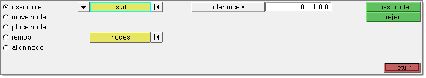
The Associate subpanel creates an association between the selected nodes and a selected piece of geometry. Nodes are projected to the geometry, provided the distance to the selected geometry is within the search tolerance. The tolerance is used to create a search sphere at each of the selected nodes. If the selected geometry is found within that search sphere, the node is projected to the closest point on the geometry. An association is made within the database between the nodes (and corresponding elements) and geometry, so any subsequent selection routines can reference either entity; for example, if creating a boundary condition (such as a force, pressure, or constraint) on the geometry, the boundary condition will be applied to the nodes and or elements upon export.

A typical use case would be to apply slight geometry revisions to an existing model.

Note:Using a large value for the tolerance may result in collapsed elements since the nodes are projected directly to the closest point on the geometry with no consideration for the element connectivity or shape.

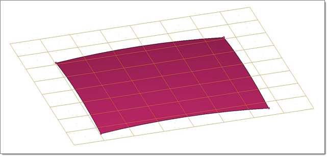
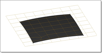
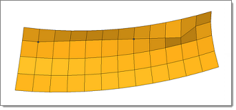
In the example below, the brown elements extend beyond the boundaries of the red surface. The elements are in a plane, but the surface is curved away from the plane.

node_edit_associate_1

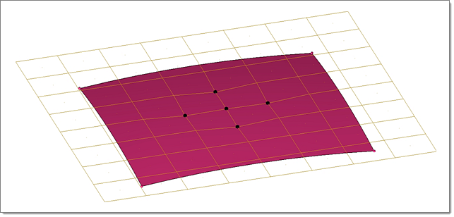
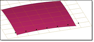
All of the nodes were selected to associate to the surface. When a small tolerance is specified, only those nodes close enough to the surface are projected and associated to it. In this example, the five highlighted nodes were associated.

Note:The distortion in the elements where only some of the four nodes are associated to the surface.

node_edit_associate_2

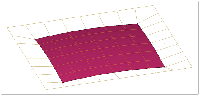
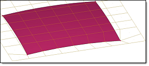
with a larger tolerance, all elements around the boundary of the surface are distorted as the nodes are projected out of their original plane and onto the surface.

node_edit_associate_3


Panel Inputs

Input

Action

(geometry collector)

Use the switch to choose between point, line, surf, or solid.  This determines the type of geometry to which the nodes will be associated.

nodes

Select the desired nodes by any method: clicking the model, using a selection window, or using the extended selection menu.

tolerance

Nodes farther from the point/line/surf/solid than this value will not become associated to it.  This allows you to perform a quick mass-node selection (such as selecting by window with SHIFT-drag) without actually associating nodes that should not be associated to the chosen geometry.


hmtoggle_arrow1Move Node

Use the Move Node subpanel to move nodes in the global coordinate system. Select the nodes to move, define a direction and a step size. Nodes can be moved in the positive or negative direction defined by the movement vector.


Panel Inputs

Input

Action

nodes

Select the desired nodes by any method: clicking the model, using a selection window, or using the extended selection menu.

(plane and vector selector)

Specify the direction for the node(s) to move, either by defining an axis, vector, or a plane (in which case the noes will move in the plane's positive normal direction as determined via the right-hand rule).

step size

This is the distance that the selected nodes will travel in the specified direction each time the move+ or move- buttons are clicked.


hmtoggle_arrow1Place Node

Use the Place Node subpanel to move a single node to a specific location on a destination surface. After selecting the surface, select the node to be placed. Once the node is selected, click the new location for that node on the surface.

node_edit_placenode_1

standard_arrow_beforeafter

node_edit_placenode_2


Panel Inputs

Input

Action

destination surf

Use this collector to pick the surface onto which you wish to place the node.

node to place

use this collector to select the desired node, then click the desired location on the selected surface.  The node relocates automatically.


hmtoggle_arrow1Remap

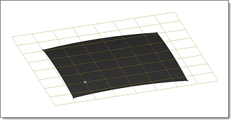
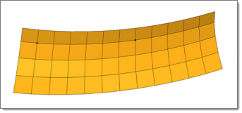
Use the Remap subpanel to remap a series of nodes to a selected line list.

In the example below, the selected nodes are mapped to the surface edge.

Note:The nodes selected become evenly distributed across the surface edge.

node_edit_remap1

standard_arrow_beforeafter

node_edit_remap2


Panel Inputs

Input

Action

node list

Select the series of nodes that you wish to remap.

line list

Select the line(s) to which you wish the node list to relocate.


hmtoggle_arrow1Align Node

Use the Align Node subpanel to snap one or more nodes to an imaginary line connecting two other selected nodes. Any number of nodes may be aligned once a line is defined.

node_edit_align1

The two nodes selected define an infinite line.

standard_arrow_beforeafter

node_edit_align2

Any nodes selected will be projected to that line.


Panel Inputs

Input

Action

1st end: node

This node defines one end of the imaginary line.

2nd end: node

This node defines the other end of the imaginary line.

Once both nodes are selected, you are prompted to pick the nodes that you wish to align.

nodes/node

Use the toggle to specify whether to select one or more nodes.

If the toggle is set to nodes, click align after you are finished selecting nodes.

use ratio

Aligns nodes using the specified ratio.

Only available when you are aligning one node at a time.


hmtoggle_arrow1Command Buttons

The following action buttons appear throughout the subpanels:

Input

Action

associate

Associates the selected nodes with the selected geometric entity.

reject

Undoes the most recent node edit.

move+

Moves the nodes in the direction specified by the specified step size.

move-

Moves the nodes opposite to the direction specified by the specified step size.

remap

Relocates nodes to a selected line list.

return

Exits the Node Edit panel, finalizing any edits made (you cannot reject an edit after leaving the panel, even if you return later.)