
|
This subpanel creates nodes by specifying (x,y,z) coordinates.
In this example, the created nodes has x=5, y=4, and z=8.
There are several methods for entering the coordinate values:
| • | Type the coordinate values manually into the input boxes. |
| • | Populate individual coordinate values using the x, y and z collectors and selecting a node graphically. |
When using each of these collectors, the respective x, y, or z coordinate value is copied from the selected node into the corresponding input box. The values can be edited as desired.
| • | Populate the coordinate and system values using the as node collector and selecting a node graphically. |
This will copy the respective x, y and z coordinate values and the reference system value from the selected node into the corresponding input boxes. The values can be edited as desired.
By default, nodes are created relative to the global system, however a local coordinate system can be specified using the system collector. This system can be rectangular, cylindrical or spherical. When a node is created, it is also assigned the specified reference system. The node is then updated to reflect any changes that are made to that system (for example translate, rotate).
|
|

|
This subpanel creates nodes at graphically selected locations on points, lines, surfaces and planes. Upon selecting the type of geometry you wish to create nodes on, you can simply click any location on such geometry in the graphics area to place a node. In the case of nodes on a plane, you must first create the plane, which is temporary and invisible, but allows you to place nodes outside of existing geometry.
Lines:
These nodes were created on the lines bordering a surface.
Surfaces:
Plane:
The plane is invisible, but coincides with the visible surface.
|
|

|
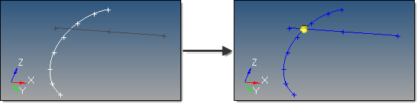
This subpanel creates a nodes at the center of the arc that best approximates the input set of nodes, points or lines.
For nodes and points input, a minimum of three must be selected.
For lines input, the selection must not result in a straight line.
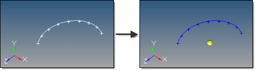
An existing arc is an ideal input.
However, almost any set of lines will also work, even if they are not connected, as long as they do not form a straight line.
An optional tolerance is available to verify whether the calculated best-fit circle is sufficient. If ignored, the best-fit circle is always calculated; otherwise, an error is returned if the input entities are not all on the circle within the specified tolerance.
|
|

|
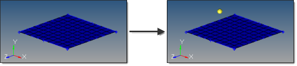
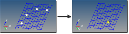
This subpanel creates nodes at parametric locations on lines and surfaces.
For lines:
| • | 0.0 <= u lower bound <= u upper bound <= 1.0. |
| • | If the lower and upper bounds are the same, only one node is created. |
| • | If the number of u nodes is specified as 1, only the lower bound is used. |
| • | The line parameterization type can be specified as either arc length or internal. Internal parameterizations depend on how the line was originally created, while arc length simply distributes the nodes uniformly. |
This example uses u lower bound 0, u upper bound 0.75, u nodes = 5, and arc length parameterization.
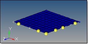
For surfaces:
| • | 0.0 <= u lower bound <= u upper bound <= 1.0. |
| • | 0.0 <= v lower bound <= v upper bound <= 1.0. |
| • | The number of u and v nodes must be >= 1. |
| • | The total number of nodes created equals (number of u nodes * number of v nodes). |
| • | The surface parametric area is scaled to the visible surface area. Nodes will be created inside the visible surface area. |
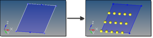
Here, u ranges from 0 to 0.75 with 5 nodes, while v ranges from 0 to 0.66 with 3 nodes.
|
|

|
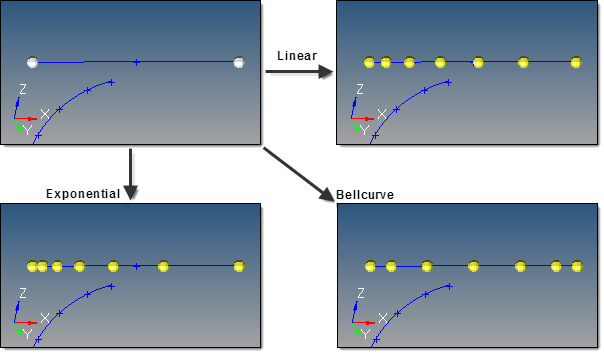
This subpanel creates evenly spaced or biased nodes on a selection of lines.
The following examples use the same input line, 7 nodes, and a bias intensity of 5.0:
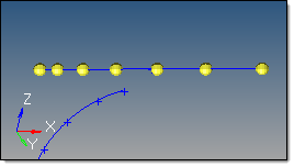
Linear bias
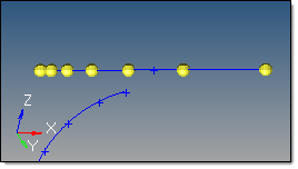
Exponential bias
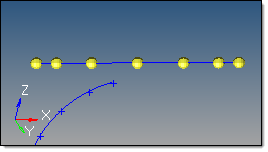
Bellcurve bias
|
|

|
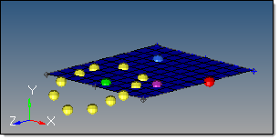
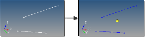
This subpanel creates evenly spaced or biased nodes by interpolating between existing nodes in space.
The input nodes are specified as a node list, with each node considered as a pair with the next node in the list. The specified number of nodes are created on a straight line between each node pair.
The example below shows the effect of adding 5 nodes between the end nodes of a line using different types of bias, with bias intensity 5.0:
| Note: | Nodes are created in 3D space, and not merely on geometry: |
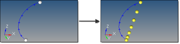
To interpolate nodes along a curved line like the one shown above, use the interpolate on line subpanel instead.
|
|

|
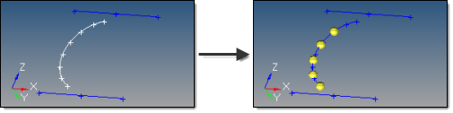
This subpanel creates evenly spaced or biased nodes by interpolating between existing nodes on a line.
The input nodes are specified as a node list, with each node considered as a pair with the next node in the list. The nodes are created on the input line between each node pair.
The input nodes are not required to lie on the selected line, as all input nodes are first projected onto the line.
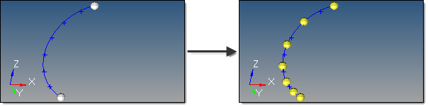
5 nodes created between 2 input nodes along a curved line, using linear biasing.
|
|

|
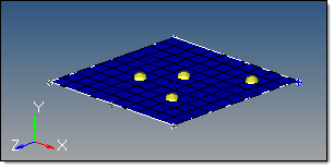
This subpanel creates evenly spaced or biased nodes by interpolating between existing nodes on a surface.
The input nodes are specified as a node list, with each node considered as a pair with the next node in the list. The nodes are created on the input surface between each node pair.
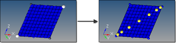
The highlighted opposing corner nodes have 7 interpolated nodes created between them, using Bellcurve biasing.
The nodes are not required to lie on the selected surface, as all input nodes are first projected onto the surface.
|
|

|
This subpanel creates nodes at the intersection of geometric entities: lines/lines, lines/surfaces, lines/solids, lines/planes, vector/lines, vector/surfaces, vector/solids and vector/plane.
A node is created at each intersection location.
For surface, solid, and plane intersections, if the input line or vector lies on the surface/solid/plane the result is undefined and unpredictable.
For vectors, the magnitude and direction of the vector do not have any effect on the result. The vector extends through the entire model space.
|
|


