Supported Solvers
- MotionSolveTM
- MATLABTM
- ADAMSTM
- SIMPACKTM
| Purpose | MotionSolve Element | ADAMS Element | Description |
|---|---|---|---|
| Apply bushing forces | FORCE_VECTOR_TWOBODY | GFORCE | Applies bushing forces and moments to the I-Body and J-Body. |
| Compute bushing forces | CONTROL_STATEEQN | GSE | Computes bushing forces and moments and the time derivatives of states associated with the bushing forces and moments. |
| Compute mount displacement velocities | CONTROL_STATEEQN | GSE | Computes the local structural deflection and rate of change of deflection given the sum of the friction, bushing, and limit forces and moments acting between the two connecting bodies. |
| Compute bushing limit forces | CONTROL_STATEEQN | GSE | Computes the forces and moments due to bushing reaching the limits of its travel. This may include material contact between the connecting bodies. |
| Compute external friction effects | CONTROL_STATEEQN | GSE | Computes the friction torque that acts in response to the relative rotational motion between the two connecting bodies. |
| Coordinate system | REFERENCE_MARKER | Marker | Defines a coordinate system on a body. In this context it defines the location where the forces are applied and the axes along which moments are computed. |
| Variable | REFERENCE_VARIABLE | Variable | Defines an algebraic state and its underlying expression. In this context they define the signals that are eventually provided as input to a GSE. |
| Array | REFERENCE_ARRAY | Array | A collector that collects several signals and provides them as input to a GSE. |
Solver Components Workflow
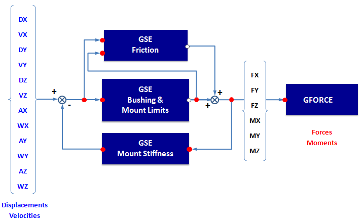
Figure 1.
GFORCE Bushing
! Frequency & Amplitude Dependent Bushing
GFORCE/id
, I= id-marker-I-Body,
, JFLOAT= id-floating-marker-J-body,
, RM= id-marker-J-body
, FX= ARYVAL(id-array-y-gse-bus,1) \  !FX
, FY= ARYVAL(id-array-y-gse-bus,2) \  !FY
, FZ= ARYVAL(id-array-y-gse-bus,3) \  !FZ
, TX= ARYVAL(id-array-y-gse-bus,4) \  !TX
, TY= ARYVAL(id-array-y-gse-bus,5) \  !TY
, TZ= ARYVAL(id-array-y-gse-bus,6) \ !TZ- GFORCE Attributes
- The following table describes the attributes of the GFORCE:
Integer Identifier Description id Integer identifying the GFORCE statement. id-marker-i-body ID of Marker on I-Body to which the GFORCE applies force and torque. id-floating-marker-j-body ID of floating Marker on J-Body to which GFORCE applies reaction forces and torques. id-marker-j-body ID of Marker on J-Body used as the coordinate system for all calculations. This Marker is also used when calculating the input displacements and velocities for the simulation model. id-array-y-gse-bus ID of the bushing GSE Y (output) array containing the forces and torques computed by the simulation model.
GSE Bushing Force and Mount Limits
This GSE computes the output forces and torques and the derivatives of the internal states associated with the RUBBER_DAMPING or HYDROMOUNT_DAMPING formulations. The required computations are performed in the use-subroutine GSESUB_BW that is located in the .dll file or shared library file.
- The number of outputs (NO) is six (6) for three forces: FX, FY, FZ; and three torques: TX, TY, TZ.
- The number of states (NS) is eighteen (18) for 6 directions, 3 states per direction.
- Example of a GSE Statement
- The following is an example of the form of the GSE statement in MotionSolve:
! Rubber Damping Formulation GSE/id , NS = 18 , NO = 6 , U = id-array-u-gse-bus , X = id-array-x-gse-bus , Y = id-array-y-gse-bus , FUNCTION = USER( , id-str-gbs-file, , id-array-preload, , id-array-offset, , id-array-scale-displacement, , id-array-scale-force, , id-str-doe-file, , id-array-mount-limits ) \ , ROUTINE = AltairBushingMotionSolve::GSESUB_BW, , AltairBushingMotionSolve::GSEXX_BW, AltairBushingMotionSolve::GSEXU_BW , AltairBushingMotionSolve::GSEYX_BW, AltairBushingMotionSolve::GSEYU_BW - Attributes of the GSE File
-
The following table lists the attributes of the .gse file:
Integer Identifier Description id Integer identifying the GSE statement. id-array-u-gse-bus ID of the ARRAY statement that provides input to this GSE. It contains a list of 12 VARIABLE ids that actually compute the required signals. Example: ARRAY/9, U, VARIABLES= 1, 2, 3, 4, 5, 6, 7, 8, 9, 10, 11, 12
Let the I Marker for the GFORCE be 1125.
Let the RM Marker for the GFORCE be 2125.
Then the 12 VARIABLES, 1-12, must have the following form:
VARIABLE/1, FUNCTION = DX(1125, 2125, 2125)
VARIABLE/2, FUNCTION = DY(1125, 2125, 2125)
VARIABLE/3, FUNCTION = DZ(1125, 2125, 2125)
VARIABLE/4, FUNCTION = VX(1125, 2125, 2125,
2125)
VARIABLE/6, FUNCTION = VZ(1125, 2125, 2125,
2125)
VARIABLE/7, FUNCTION = AX(1125, 2125)
VARIABLE/8, FUNCTION = AY(1125, 2125)
VARIABLE/9, FUNCTION = AZ(1125, 2125)
VARIABLE/10, = WX(1125, 2125, 2125)
FUNCTION
VARIABLE/11, = WY(1125, 2125, 2125)
FUNCTION
VARIABLE/12, = WZ(1125, 2125, 2125)
FUNCTIONid-array-x-gse-bus ID of the ARRAY statement holding the GSE states. Example: ARRAY/10, X
id-array-y-gse-bus ID of the ARRAY statement holding the GSE outputs. Example: ARRAY/11, Y
The GSE has the following 6 outputs:
- Force acting at I Marker origin along the x-axis of the J Marker
- Force acting at I Marker origin along the y-axis of the J Marker
- Force acting at I Marker origin along the z-axis of the J Marker
- Torque on I Marker measured about the x-axis of the J Marker
- Torque on I Marker measured about the y-axis of the J Marker
- Torque on I Marker measured about the z-axis of the J Marker
id-str-gbs-file ID of the STRING statement that contains the name of the .gbs property file. The GSE reads this file to obtain all required data. Example: STRING/12, S=/usr/people/mark/propertyFile/sample.gbs
id-array-preload ID of the ARRAY statement containing preloads for the 3 force and 3 torque directions. Example: ARRAY/13, NUM=100, 200, 300, 700, 800, -900
If id-array-preload is less than or equal tozero, then the preload default is zero.
id-array-offset ID of the ARRAY statement containing the 3 translational and 3 rotational displacement offsets. Example: ARRAY/14, NUM=0.0, 0.0, 1.3, -25D, 10D, 15D
If id-array-offset is less than or equal to zero, the offsets default to 0.0.
id-array-scale-displacement ID of the ARRAY statement containing the 3 translational and 3 rotational displacement scales. Example: ARRAY/15, NUM=1.0, 1.0, 1.0, 57.29578, 57.29578, 57.29578\
If id-array-scale-displacement is less than or equal to zero, then the scales default to 1.0.
id-array-scale-force ID of the ARRAY statement containing the 3 force and 3 torque scales. Example: ARRAY/16, NUM=9.81, 9.81, 9.81, 1.0, 1.0, 1.0
If id-array-scale-force is less than or equal to zero (0), then the force scales default to 1.0.
id-str-doe-file ID of the STRING statement with the path name of a file containing variations of parameters in the .gbs property file. The parameter values in the doe file override those in the .gbs property file. id-str-lim-file If the id is positive then the software interprets the ID as the id of the STRING statement containing the path and name of a file containing impact parameters for mount limits. Example: STRING/18, S= C:\mark\property Files\sample.gbi
-or- id-array-mount-limits If the id is negative then the absolute value is interpreted as the id of an ARRAY statement containing the ids of 6 other ARRAY statements containing the impact parameters for 3 translational and 3 rotational directions. Example: ARRAY/19,NUM = 101, 102, 103, 104, 105, 106
The array contains a list of 6 ARRAY ids. Each of these ARRAY’s contains 10 parameters.
Each of these referenced ARRAY's has the following form:
ARRAY/id, NUM = KN, EN, CN, DN, LN, KP, EP, CP, DP, LP
The 10 parameters have the following meaning:
- KN : Stiffness Negative
- EN : Exponent Negative (left)
- CN : Damping Negative
- DN : Penetration for full damping Negative
- LN : Gap Negative (left)
- KP : Stiffness Positive
- EP : Exponent Positive (right)
- CP : Damping Positive
- DP : Penetration for full damping Positive
- LP : Gap Positive (right)
Note: If the ID is zero or omitted, then mount limits are inactive.
GSE Mount Stiffness
- Example of Mount Stiffness
- The following is an example of the form of the mount
CONTROL_STATEEQN:
GSE/id-gse-mou
, NS = 6
, NO = 6
, U  = id-array-u-gse-mou
, X  = id-array-x-gse-mou
, Y  = id-array-y-gse-mou
, FUNCTION = USER(id-array-mou-k, id-array-mou-c, id-array-mou-act)\
, ROUTINE = boucwen_gse::GSESUB_MOUNT,
,   boucwen_gse::GSEXX_MOUNT
,   boucwen_gse::GSEXU_MOUNT
,   boucwen_gse::GSEYX_MOUNT
,   boucwen_gse::GSEYU_MOUNT
The attributes of the mount GSE are described below:Integer Identifier Description id-gse-mou Integer identifying the GSE statement. id-array-u-gse-mou ID of the ARRAY statement that provides input to this GSE. The U ARRAY holds the identifiers of VARIABLEs statements whose values are the forces. Example: ARRAY/51, U, VARIABLES= 51, 52, 53, 54, 55, 56
Let the I Marker for the GFORCE be 1125.
Let the J-FLOAT Marker for the GFORCE be 2124.
Let the RM Marker for the GFORCE be 2125.
Then the 6 VARIABLES, 51-56, must have the following form:
- VARIABLE/51, FUNCTION = FX(1125, 2124, 2125)
- VARIABLE/52, FUNCTION = FY(1125, 2124, 2125)
- VARIABLE/53, FUNCTION = FZ(1125, 2124, 2125)
- VARIABLE/54, FUNCTION = TX(1125, 2124, 2125)
- VARIABLE/55, FUNCTION = TY(1125, 2124, 2125)
- VARIABLE/56, FUNCTION = TZ(1125, 2124, 2125)
id-array-x-gse-mou ID of the ARRAY statement containing the internal states for this GSE. Example: ARRAY/52, X
id-array-y-gse-mou ID of the ARRAY statement that provides the GSE outputs . The outputs are the 6 components combined I-Body and J-Body structural deflections and the 6 components of the structural velocities. Example: ARRAY/53, Y
The contents of the Y ARRAY are:
- Combined l- & J-Body structural deflection along XJ
- Combined l- & J-Body structural deflection along YJ
- Combined l- & J-Body structural deflection along ZJ
- Combined l- & J-Body rotational structural deflection about XJ
- Combined l- & J-Body rotational structural deflection about YJ
- Combined l- & J-Body rotational structural deflection about ZJ
- X-velocity of structural deflection along XJ
- Y-velocity of structural deflection along YJ
- Z-velocity of structural deflection along ZJ
- WX-velocity of structural deflection about XJ
- WY-velocity of structural deflection about YJ
- WZ-velocity of structural deflection about ZJ
id-array-mou-k ID of the ARRAY containing the combined local structural stiffness of I-Body and J-Body. The stiffness coefficients (kx, ky, kz, ktx, kty, ktz) must be positive real numbers. An example is shown below. Example: ARRAY/54, IC, NUM = 123.3, 234.5, 345.6, 987.6, 876.5, 765.4
id-array-mou-c ID of the REFERENCE_ARRAY statement giving the combined local structural damping of I-Body and J-Body. The camping coefficients (cx, cy, cz, ctx, cty, ctz) must be positive real numbers. An example is shown below. Example: ARRAY/55, IC, NUM = 1.233, 2.345, 3.456, 9.876, 8.765, 7.654
id-array-mou-act ID of the ARRAY specifying the activity of local structural deflection per direction. The activity coefficients (act-x, act-y, act-z, act-rx, act-ry, act-rz) must be zero (0) or one (1). A value of zero (0) turns off the structural deflection, while a value of one (1) turns on the structural deflection. Example: ARRAY/56, IC, NUM = 1, 1, 0, 0, 1, 1