BQ Card
This card defines a mesh of surface triangles in the shape of a flat quadrangle.
On the Construct tab, in the Surfaces group,
click the ![]() Quadrangle (BQ) icon.
Quadrangle (BQ) icon.
Note: For creating planar surface meshes, in general the PM card would be preferred over the
BQ card.
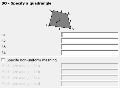
Figure 1. The BQ - Specify a quadrangle dialog.
Parameters:
- S1, S2, S3, S4
- The points S1 to S4 are the four corner points of the quadrangle. These points should have been defined previously with the DP card.
- Specify non-uniform meshing
- Usually a quadrangle is meshed according to the edge length specified with the IP card. When creating, for example, small microstrip lines it may be required to use a finer mesh size in a particular direction. Check this item if finer meshing is required along any edge. The mesh sizes are in metres and are scaled by the SF card.
- Mesh size along side a:
- The mesh size along edge S1–S2.
- Mesh size along side b:
- The mesh size along edge S2–S3.
- Mesh size along side c:
- The mesh size along edge S3–S4.
- Mesh size along side d:
- The mesh size along edge S4–S1.
The points have to be defined with DP cards before the BQ card and the points are connected in the order that they appear in the BQ card.
In principal the BQ card can create all types of quadrangles, including parallelograms. The difference is that the BP card creates a regular subdivision.
The direction of the normal vector ( ) of the subdivided triangles is determined by the right hand rule through all the corners. This direction is only important when used with the physical optics (PO card) or with dielectrics (ME card) or for the CFIE (CF card).Examples of BQ card usage
The mesh shown below was created with a BQ card using uniform meshing.

Figure 2. Example of a uniform mesh in the shape of a quadrangle created with the BQ card.

Figure 3. Example of a inhomogeneous mesh created with the BQ card.