Links
Links connect the assembly of blocks in a diagram.
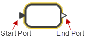
Each link connects to a block via a start or end port on the block:
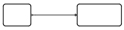
The following figure shows a diagram with two blocks connected with a regular link:
Adding and Removing Links
-
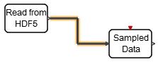
To add a link, locate two blocks that you want to connect. Click a port on the
first block, then click a port on a second block.
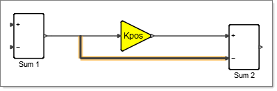
A link appears. If the ports are not aligned, an orthogonal link appears with a knee in the middle:
 Note: The copy/paste operation is not applicable for adding links.
Adding Points to Links
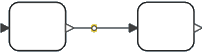
You can add points to an existing link from which you can attach other links.
Place your cursor on a link, then left-click twice. An intermediate point
appears on the link:
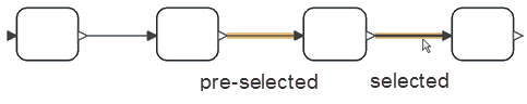
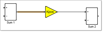
Selecting and Displaying Links
-
Click to select the link. The software displays the status of the link as
follows:
- Link Display
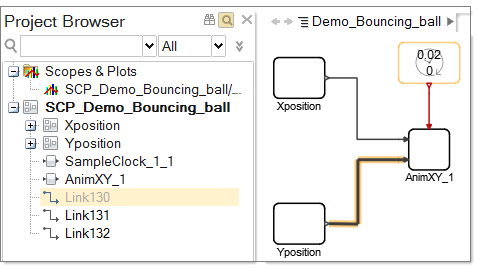
- The Project
Browser includes a filter to show or hide
different object types. If the filter is turned on to display links, then
every selected link in the block diagram is also selected in the Project Browser. The following
figure shows you a model of a bouncing ball diagram with Link 130
selected:
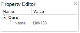
- The Property Editor displays the name, id, source,
and destination for a selected link.
Moving Link Points and Segments
You can move links and points as required for your model.
- To move a point on a link, select any point other than the start and end point, as these are confounded with the ports. Move the point as required.
- To move link segments, select one or more link segments and move as required. By default, the orthogonal alignment of the links is preserved.
Splitting Links
Split an existing link between two blocks to create a new connection in a diagram.
-
Select an existing link segment where you want to connect a block:
-
Press and hold Alt, then left-click and drag your mouse
to the port of the block that you want to connect.
A new link extends from the existing link to the new block.
Link Display
Links are color-coded by type: regular, explicit, implicit or bus.
Link types are displayed with the following default colors:
- Black
- Regular, explicit links.
- Red
- Event-handling links.
- Blue
- Implicit links, for example links to connect implicit blocks such as Modelica-like blocks used for acausal modeling.
- Green
- Bus links.