Observation Directions
Observation directions are used when inspecting the generated results at the user interface, such as the generated Far Field results. This option is used for letting the user add, modify and delete these cuts. Select Output > Observation Directions to show the panel described in the figure:
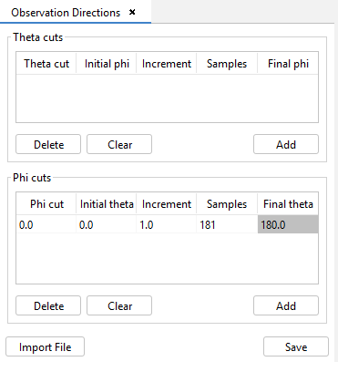
Figure 1. Observation Directions panel
In order to make the calculations useful, the user should configure observation directions where the electrical field will be calculated. These directions will be selectable by the user after the calculations have been done when inspecting the results. To add a cut, either a theta or a phi cut, press the Add button to add a row to the associated table, and fill the values in the row.
- Theta Cut / Phi Cut this is the value at which theta will be fixed in a conical cut (theta cut) or at which phi will be fixed in a planar cut (phi cut).
- Initial Phi / Initial Theta this is the initial value for the sweep in that observation direction cut.
- Increment this is the value the angle will be incremented in each iteration for the sweep.
- Samples the number of samples to take for the cut.
Final Phi / Final Theta is a non-editable value that will display the final angle for the sweep. This value is actually calculated using the following simple formula Initial + Samples * Increment.
Rows can be deleted by selecting them in the tables and pressing Delete. Press the Save button when done.
Additionally, this information can be included using an external file, pressing the 'Import File' button and uploading the file with the data. The content of this file will have a row for each cut to enter
- A 4-field format separated by the space character. Each field refers to the angle theta, phi, steps and samples of the cut.
- A two-field format separated by the space character, detailing the angles theta and phi to be calculated are detailed (in this case, the sample data is assumed to be 1).