Coupling
Figure 1. Output Menu
If the user selects theCouplingoption (which is only available ifCouplingsimulation type is enabled), the following panel is shown:
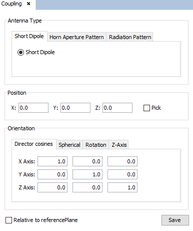
Figure 2. Passive antenna configuration panel
The following parameters may be edited:
-
Antenna Type the passive antenna can be:
- Short dipole: the passive antenna is defined by a short dipole.
- Horn aperture pattern: The user has to select the pattern file of a horn antenna and its polarization vector (given by its real and imaginary parts for each coordinate). The required format of the radiation pattern file is described in DIA Files. This option will be selected when the pattern file to be used as the definition of the passive antenna, correspond to a horn aperture.
- Radiation pattern file: The user has to select the pattern file of an antenna. The format of the radiation pattern file can be REV, RV2 or 3DE, and the polarization can be linear ( LIN) or circular ( CIR). The required format of the radiation pattern file is described in DIA Files. This option will be selected when the passive antenna is defined by a radiation pattern file.
- Position-Coords: location of the passive antenna (from the keyboard or using the mouse with ' Pick Point Edition' option).
- Orientation Director Cosines: orientation of the passive antenna coordinate system related to the absolute coordinate system.
If all the information is correct, the antenna will be shown on the screen. A red parabola represents the active antenna and a magenta parabola the passive antenna. The axis of the antenna is also visualized. If the antenna is not visualized on the screen after pressing Save button, the most common reason is that the radiation pattern has not been found in the NewFasant installation folder.