Pattern File Array
This option allows the user to add an array of pattern file antennas to the simulation. When the user selects this option in the menu, the following panel will appear:
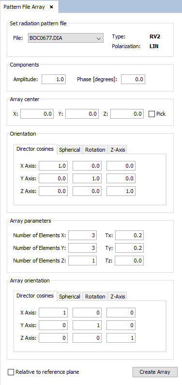
Figure 1. Pattern File Array panel
In this panel, the user can specify the parameters of each pattern file in the same way as in the "Pattern File Antenna" panel (as described in the previous section). Additionally, the user can specify parameters regarding the creation of the array:
- The point specified in the "Array center" panel is the point where the array center will be located. By checking the "Pick" check box, the user can pick the desired point in the geometry panel and the textboxes will be automatically filled with the point coordinates.
- The "Array parameters" panel contains the values that will determine the number of antennas created along each axis ( Number of Elements X, Number of Elements Y and Number of Elements Z), as well as the separations between each adjacent antenna along each axis ( Tx, Ty and Tz).
- The "Array orientation" panel allows the user to specify the directions of the axes considered when creating the array. By default, the array axes are the same as the absolute X, Y and Z axes when the "Relative to reference plane" option is selected.
If the "Relative to reference plane" check box is selected, the axes given in the "Array orientation" panel, as well as the point given in the "Array center" panel will be transformed according to the current reference plane coordinate system.
After specifying the parameters, the user needs to click on the "Create Array" button for the array of pattern files to be added to the simulation.