Diagrams
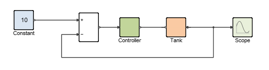
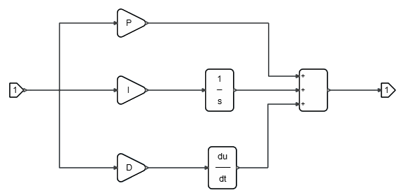
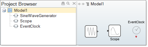
A diagram is an assembly of blocks, links, annotations and other components inside of a model.
Creating Diagrams
The process to create a diagram includes adding, linking, and assembling blocks in the modeling window. The blocks in a diagram can include predefined blocks from the library palettes or user-defined blocks.
Adding Library Blocks to a Diagram
Add a library block to a diagram from the Palette Browser.
-
To open the Palette Browser, press
F6 or select .
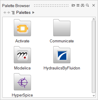
The Palette Browser displays the installed library palettes.
Adding User-Defined Blocks to a Diagram
Add or import a user-defined or customized block that is not associated with the installed libraries into a diagram. These blocks are stored as .scb files.
Copying Blocks to a Diagram
From inside of a diagram, you can copy a block and then paste it into the current model or into any open model.
- In a diagram, select a block you want to copy, right-click, and from the context menu, select Copy.
- Select a diagram in the current model or any open model, right-click and from the context menu, select Paste.
Duplicating Blocks in a Diagram
The Duplicate option lets you easily add multiples of a block into a diagram.
-
From the context menu, select Duplicate.
An exact duplicate of the block appears in the diagram.

Linking Blocks in a Diagram
Connect blocks with links that extend between the ports on the blocks.
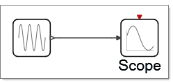
Diagram Parameters
Diagram parameters are variables that can be used for defining block parameters.
Overview of Diagram Parameters
Most blocks contain parameters with user-defined values. Block parameter values can be any OML valid expression. Such an expression may be a simple number, for example 12; an expression involving numbers and strings, such as sin(cos(3)-1); or even an expression involving OML variables such as exp(a^2). In the latter case, the variable a is a diagram parameter.
Diagram parameters are OML variables that are associated with a diagram. They can be used in the definition of block parameter values for blocks within the diagram. The set of these variables and their values constitute an OML workspace.
The parameters of a diagram D are defined by the context of the diagram D, the contexts of the diagrams that include D, and the model Initialization script. For example, let D0, D1, … Dn represent the parent diagrams of D with Dn being the closest and D0 the furthest parent. In this case, the scoping rule in the software is such that the value of a diagram parameter is given by the definition of the corresponding variable if the variable is defined in the context of D. If the variable is not defined, the definition of the closest parent diagram provides the value of the parameter.
In the absence of such a definition, the definition in the Initialization script of the model provides the value of the parameter. More specifically, the workspace of Diagram D, which is the set of diagram D parameters, is obtained as follows:
- The Initialization script of the model is evaluated resulting in a workspace, the elements of which are called model parameters.
- The context of D0 is evaluated in this workspace resulting in the workspace of Diagram D0.
- The context of D1 is evaluated in the workspace of Diagram D0, yielding the workspace of Diagram D1, and so on.
- Finally the workspace of Diagram D is obtained by evaluating its context in the
workspace of its parent, Diagram Dn. Note: The evaluations of the diagram and block parameters are done at run time. Therefore, if the Initialization script or a diagram context contains instructions to load data or run an external script defining new variables, the values of these variables may change if the external files are modified from the time of one simulation run to another. If the expression corresponding to a block parameter value refers to a variable that is not a diagram parameter, an error occurs at run time.
Diagram parameters play an important role in the masking operation. A masked super block does not contain any blocks with parameter definitions that reference variables outside of the super block. All required variables must be defined inside the super block or be a parameter of the masked super block. The Auto Mask operation enforces this condition by searching for all variables used within the super block but defined outside of it, and applying the variables as super block parameters. When a model is simulated in batch mode from OML, for example for optimization purposes, an OML workspace can be provided to define or redefine model parameters (variables in the workspace resulting from the evaluation of the Initialization script). Specifically, the provided workspace is included in the workspace resulting from the evaluation of the Initialization script, overwriting existing variables in case of conflict.
The resulting workspace then constitutes the model parameters, which are used in the rest of the model. This mechanism allows for the modification of diagram parameters, and thus blocks parameter values without modifying the .scm model file.