Create the Activate Model
The behavior of the power button and the LED light is defined in the following
Activate model:
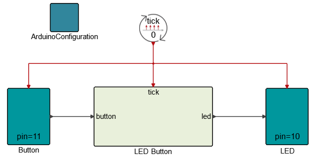
The model contains the following components:
- An Arduino Configuration block used in simulation mode to open the serial communication port with the Arduino board.
- A Button block representing the hardware button connected to pin 11 of the Arduino board.
- An LED button representing the hardware to which the LED is connected to pin 10 of the Arduino board.
- A button super block containing the dynamics of the system. When the button is pressed, the LED switches on for two seconds, then switches off.
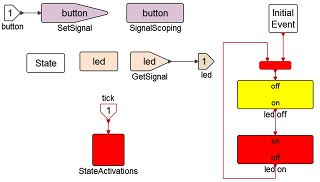
The model uses a state machine construction in Activate. This method of constructing state machines is presented in the Activate Extended Definitions .pdf file.
In this example, the model system can be in two different states: one where the LED
is on, and another where it is off:
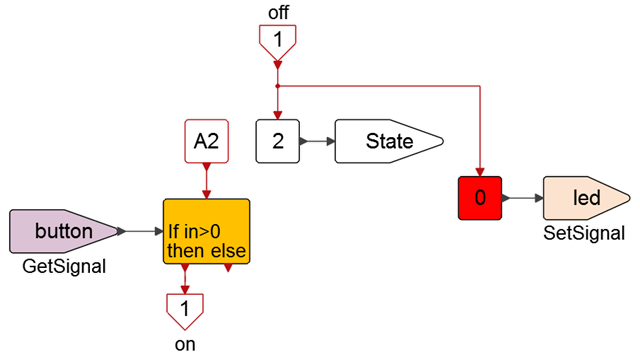
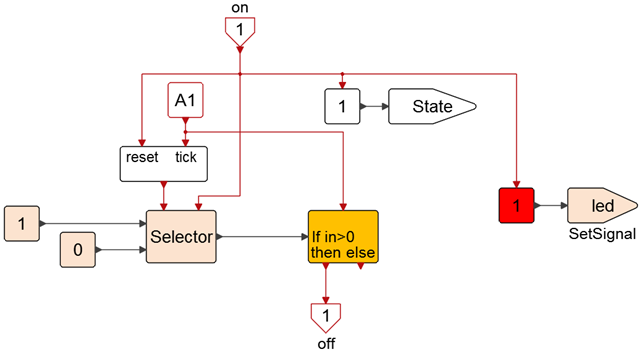
The on signal changes the value of state to 1 (thus deactivating the state represented by the LED-off super block and activating the LED_on super block state. It also sets the signal LED to 1 (turning on the LED) and resets a counter.
The subsequent successive A1 activation signals then increments a counter (through tick input) incrementing the count until the desired value (chosen so that the process takes 2 seconds).