Use the Move tool to position the car inside of the wind
tunnel.
When positioning the car, it is advisable to change the view to orthographic
projection using the icon on the View Controls
toolbar.
In the Model Browser, click the top-most assembly to select
the entire car.
From the Home group, click the
Move tool.
Figure 1.
The Move tool will initially be positioned at
the centroid of selected objects. Figure 2.
Click a graphical manipulator then do one of the following:
Drag the graphical manipulator to translate or rotate objects in the selected direction(s).
Enter a precise value in the microdialog and
press Enter.
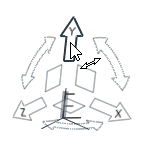
To
Do This
Translate along an axis
Click the X, Y, or Z arrow. Figure 3.
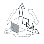
Translate along a plane
Click the XY, XZ, or YX plane square. Figure 4.
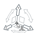
Translate freely in 3D space
Click the origin of the Move
tool. Figure 5.
Tip: Use the icons in the microdialog to align the tool to a
part or the global axes.
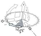
Rotate around an axis
Click a curved arrow. Figure 6.
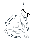
Rotate freely
Click at the tip
of the X, Y, or Z arrow and drag. An axis line
appears and the unresolved rotation is prompted on
release. Figure 7.
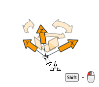
Position the front end of the car at a certain distance from the inflow.
Position the Move tool at the front end of the
car by holding the Shift key, clicking on the
origin of the tripod, then dragging it while pressing the left mouse
button.
Figure 8.
Once the triad is positioned, release the left mouse button and
Shift key, then click on the center of the
origin to open the dialog for the x, y, and z coordinate of the
origin.
The x coordinate of the tripod's origin represents the absolute
position of the car nose.
Type the desired distance into the x text field to move the car to the
correct position.
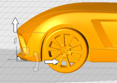
A similar technique can be used if a certain ride height, distance of the
fender lip to the ground or underbody to the ground needs to be modeled. A
reasonable positioning in the z direction, upwards, is when the wheels are
slightly penetrating the ground of the wind tunnel.Figure 9.
 icon on the View Controls
toolbar.
icon on the View Controls
toolbar. Figure 1. The Move tool will initially be positioned at the centroid of selected objects.
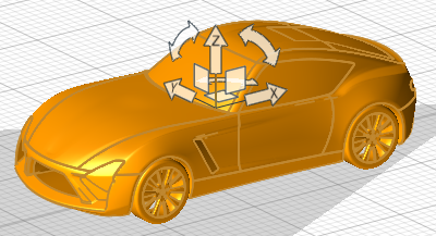
 at the tip
of the X, Y, or Z arrow and drag. An axis line
appears and the unresolved rotation is prompted on
release.
at the tip
of the X, Y, or Z arrow and drag. An axis line
appears and the unresolved rotation is prompted on
release.