Tutorial: Die Design

Learn about the basics of die design.

In this lesson, you will learn about:
  • Defining the part
  • Setting the draw direction
  • Creating the binder
  • Creating the addendum
  • Finalizing the draw die

Change the Default Units

In Inspire Render, the default unit of measurement is centimeters and grams. In this tutorial, we'll be using millimeters and kilograms.

  1. On the Help menu, click the Preferences button.
  2. In the Preferences window, click Inspire Render > Units.
  3. Under Current session units, select the following units:
    Length mm
    Mass kg
    Area mm2
    Volume mm3
    Density kg/mm3
  4. Click Apply.
  5. Click Save as Defaults.
  6. Click OK.

Import the File

First, download and unzip this file: bpillar_mod_w_mod_binder.zip.
  1. On the File menu, select Import.
  2. Browse to the bpillar_mod_w_mod_binder.x_b file.
    The model is loaded.

Define the Part

Select a part and define the thickness and position.

  1. On the ribbon, click the Die Design tab.
  2. Click the Part icon.

  3. Click the Assign icon.

  4. Select the part, shown below in yellow.

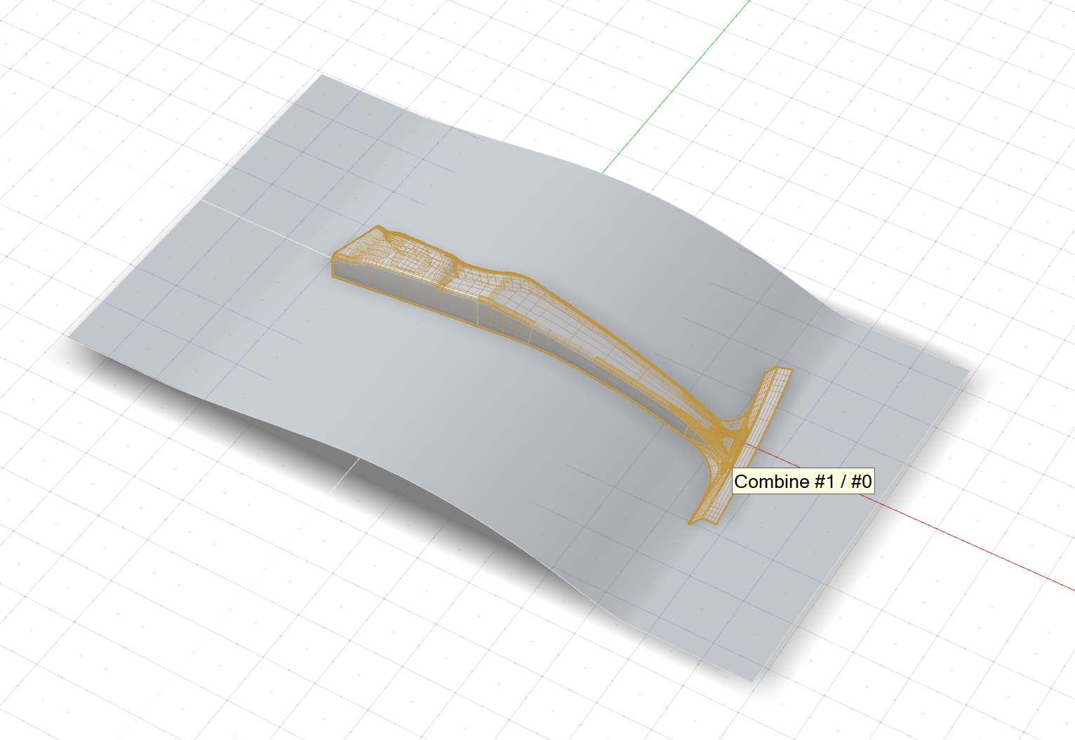
    Note: Red dots indicate discontinuity vertices (locations where edge discontinuity occurs) or corners. Ribs will be automatically added here when you create the addendum.

  5. In the guide bar, change the Thickness to 1.0 mm.
  6. By default, the part is designated as the Bottom Face of the thin solid. In this tutorial, we'll keep the default setting.
  7. Right-click and mouse through the check mark to exit, or double-right-click.

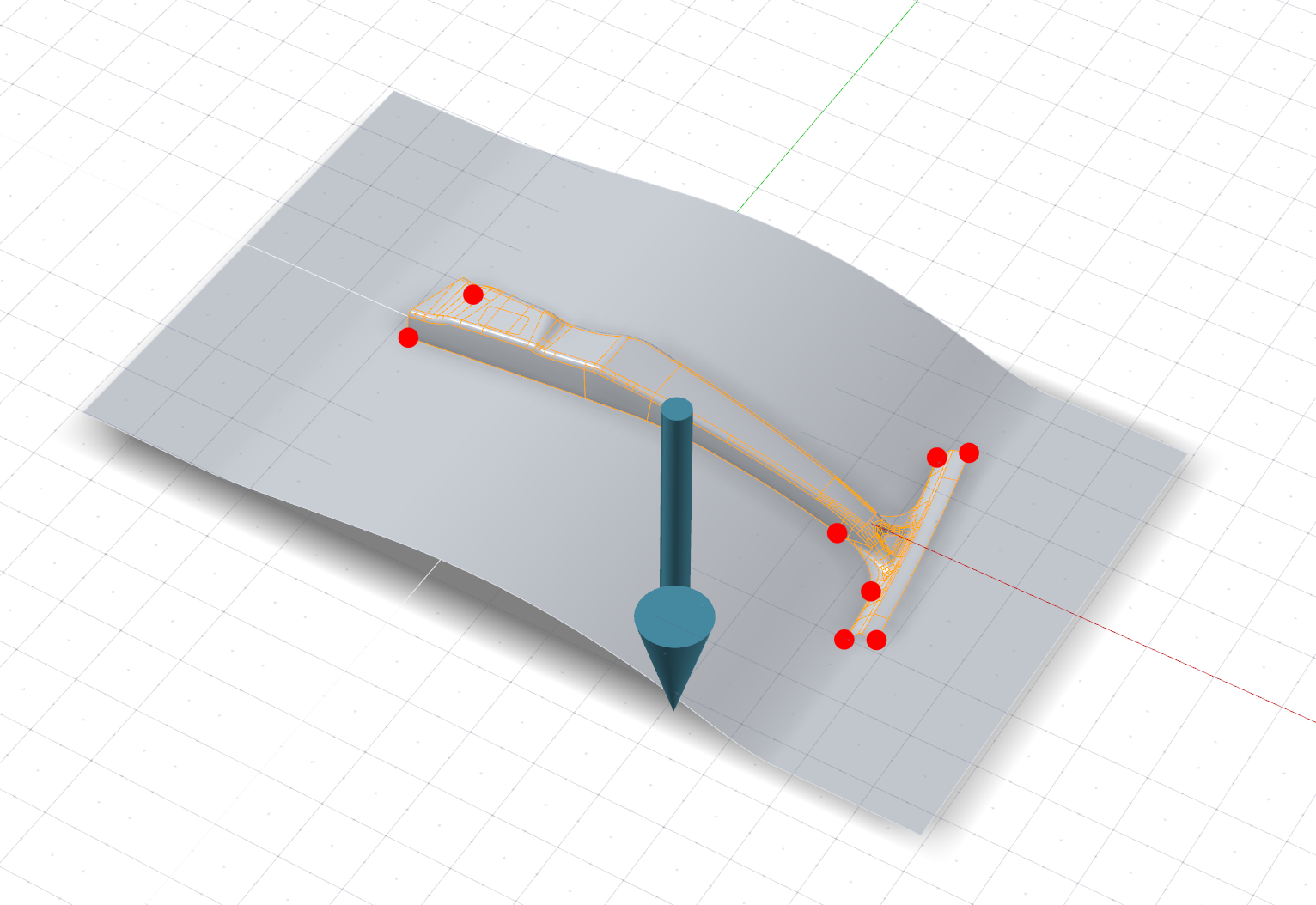
Set the Draw Direction

Adjust the draw direction to minimize the depth and avoid negative drafts with the help of the Depth Box and Draft Analysis.

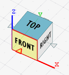
On the NaviCube, click Front to rotate the model to the front view.

  1. Click the Draw Direction icon.

  2. To display the draw depth, in the guide bar, select Depth Box.
  3. To display severe negative drafts in red and marginal negative drafts in yellow, select Draft Analysis.
  4. Set the draw direction:
    1. Click the Phi Angle arrow.

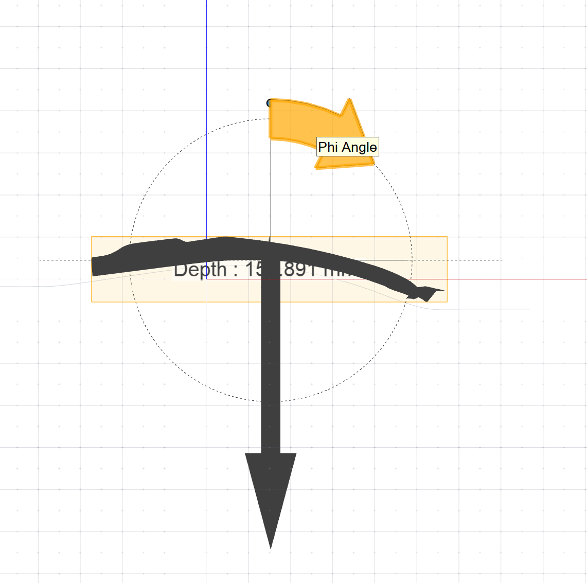
    2. Enter an angle of 4.0 deg.
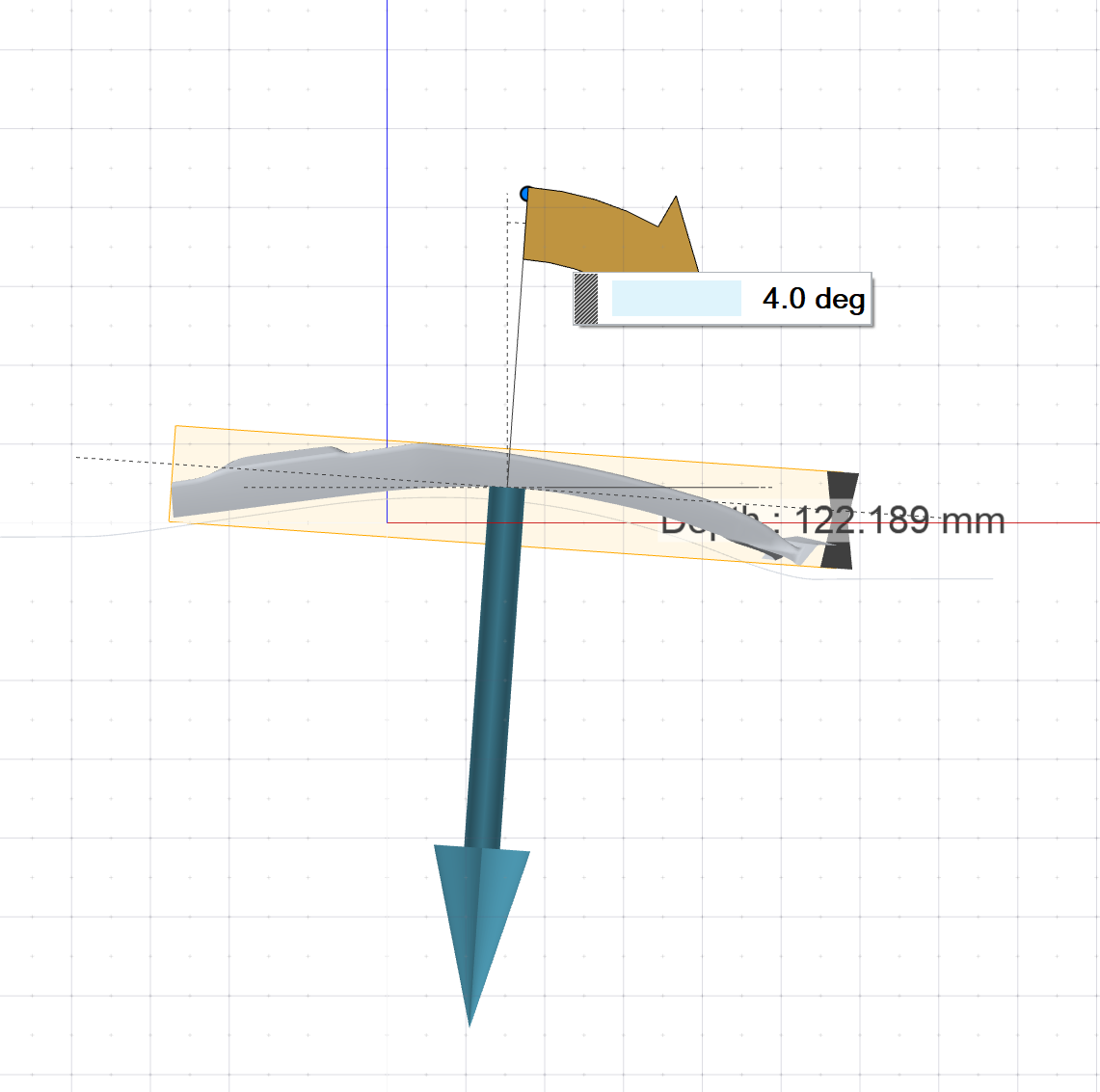
  5. Right-click and mouse through the check mark to exit, or double-right-click.

Create the Binder

Define a binder for the draw die. In this tutorial, we'll assign an existing surface as the binder.

  1. Click the Binder icon.

  2. Click the Assign icon.

  3. Selectable edges are green. Click one of these addendum start edges.

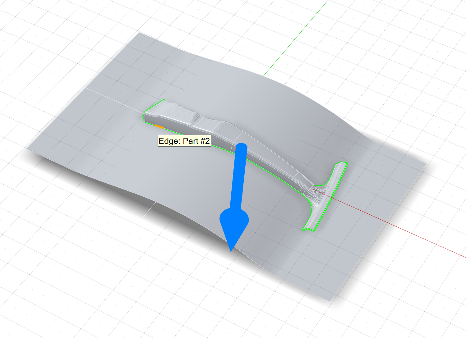
    Because Chain selection is the default selection method, all connected edges are selected automatically and now displayed in dark blue.
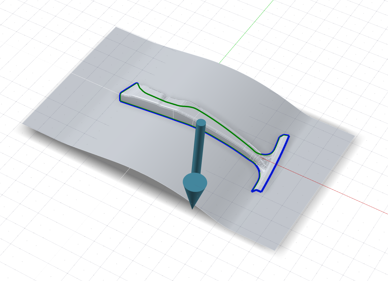
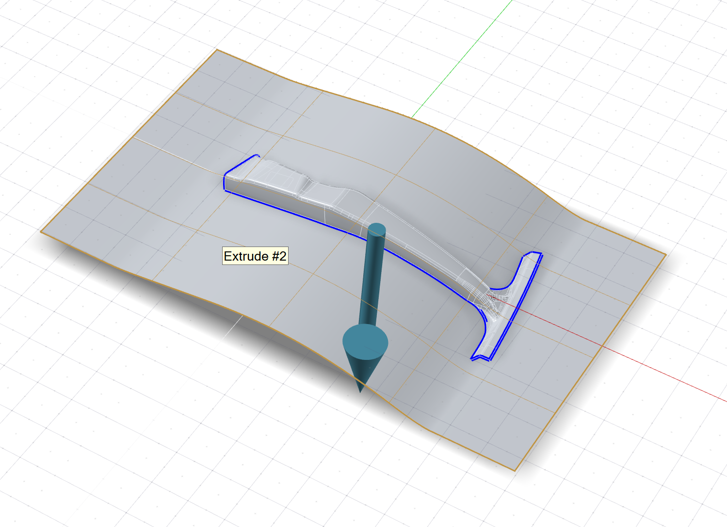
  4. Assign the binder:
    1. In the guide bar, select Binder.
    2. Select the surface (Extrude #2), highlighted in yellow below.

      Tip: To display the maximum distance between the part and binder, in the guide bar, turn on Max Draw Depth.
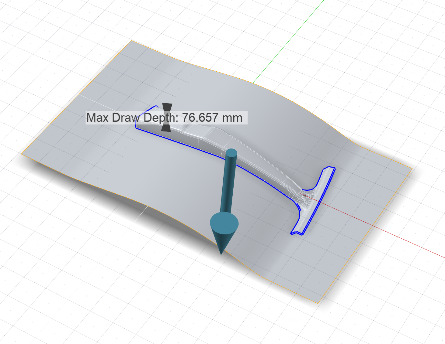
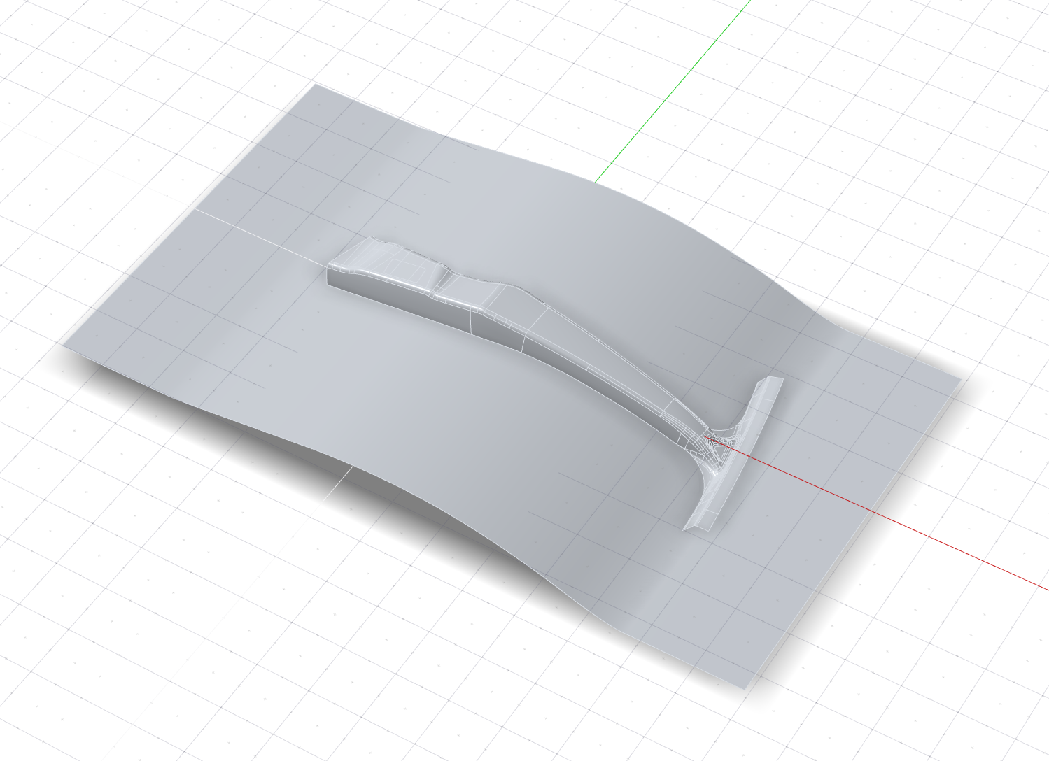
  5. Right-click and mouse through the check mark to exit, or double-right-click.

Create the Addendum

  1. Click the Addendum icon.

  2. Select the start edges of the addendum. Selectable edges are green.
    Note: The binder for the addendum is implicitly assigned from the selected edges.
  3. To select where you want to automatically create ribs, in the Control Panel, for Auto create rib locations, select All Vertices. Ribs will be automatically created at all vertices, points, and locations on the part edge. This includes vertices on the edge, T-intersection vertices, and discontinuity vertices.
  4. Zoom in on the model and use the NaviCube to rotate the model to the Top view.
  5. Select the vertices along the horizontal.
    1. Use box selection.

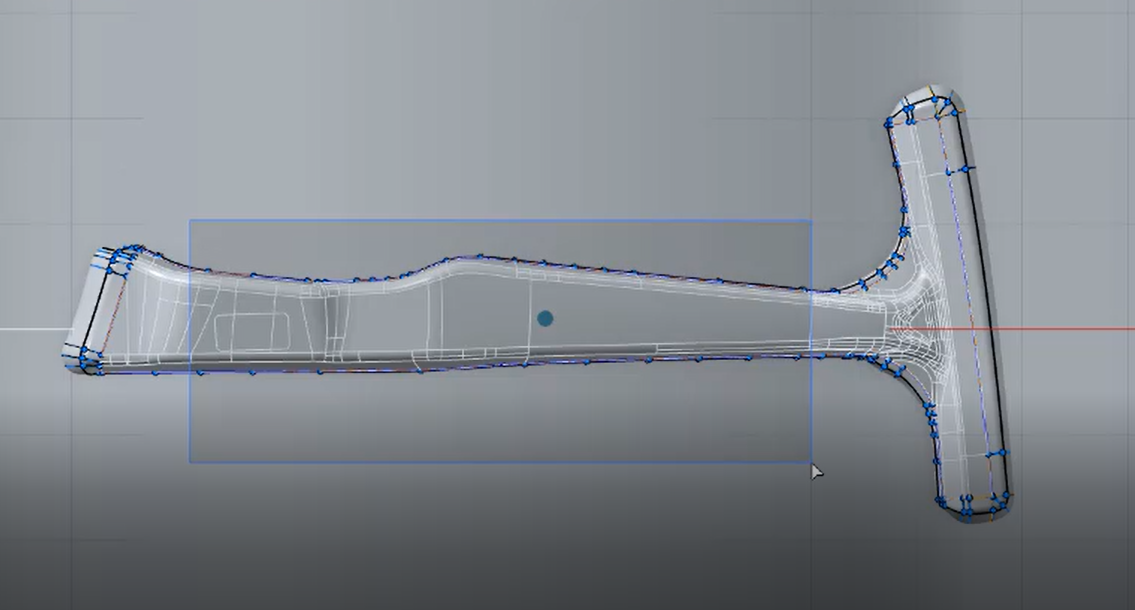
    2. You may need to zoom in to make sure all vertices are selected. While holding down Ctrl, box select additional vertices.
  6. In the guide bar, change the rib type to Straight Line. This rib type extends from the part with a line, ensuring tangent continuity, and is continuous down to the binder.
  7. Rotate the model towards the Front/Back view and zoom in on the rib as shown in this video.
  8. Select this rib. In the microdialog, change the Addendum configuration to Auto Decide Tangency, which uses G0 when G1 is not feasible.
  9. In the guide bar, select Copy Rib.
    1. Select the next rib to the left, which we want to copy.
    2. Hover along the edge. Blue dots are displayed where you can paste a copy of the rib. Alt+click to place a copy.
    3. Zoom out and rotate the model towards the Front view. Alt+click near the end, as shown in this video, to place another copy.
  10. Zoom back out and then zoom in on the rib we just copied.
  11. Select this source rib. In the guide bar, select Edit Ribs.
      1. Change the Radius to 8.0 mm.
      2. Change the Length to 10.0 mm.
  12. In the guide bar, select Pass Rib Parameters.
    1. Right-click, and then select Select ribs of same type.
    2. Right-click, and then select Update.
  13. Zoom out and rotate the model towards the Front view.
  14. In the Control Panel, turn on Draft Analysis.
    1. Rotate the model towards the Back view. Notice the red areas, indicating severe negative drafts. Zoom in on the area shown in the video. We’ll need to edit the ribs here.
    2. Turn off Draft Analysis to return to editing mode.
  15. In the guide bar, select Edit Ribs.
      1. Select the rib shown in the video.
      2. Change the Length to 10.0 mm.
  16. In the guide bar, select Copy Rib.
    1. Select the rib shown in the video.
    2. Hover along the edge. Blue dots are displayed showing where you can paste a copy of the rib. Alt+click to place a copy.
  17. Smoothen the addendum wall where it intersects the binder:
    1. In the guide bar, turn on Apply smoothing.
    2. In the guide bar, turn off Apply smoothing to return to editing mode.
  18. In the guide bar, select Edit Ribs.
    1. Select the rib shown in the video.
    2. In the microdialog, change the Addendum configuration to Auto Decide Tangency, which uses G0 when G1 is not feasible.
  19. Again, smoothen the addendum wall where it intersects the binder:
    1. In the guide bar, turn on Apply smoothing.
    2. Zoom out to evaluate the smoothened edges.
    3. In the guide bar, turn off Apply smoothing to return to editing mode.
  20. In the guide bar, select Edit Ribs.
    1. Select the rib shown in the video.
    2. In the microdialog, change the Addendum configuration to Auto Decide Tangency, which uses G0 when G1 is not feasible.
  21. Right-click and mouse through the check mark to exit, or double-right-click.

Finalize the Draw Die

  1. Click the Die icon.

  2. Select a binder.
  3. For the fillet method, select Loft Fillet.
    A fillet is created using the Loft tool from Inspire Render.
  4. Right-click and mouse through the check mark to exit, or double-right-click.