Inspire Mold is a modern simulation-driven design
environment that lets you test, validate, correct, and optimize the design of
injection-molded components.
The software provides an easy five-step workflow that designers and product engineers can
leverage to determine ideal part designs, material usage and manufacturing processes
long before any physical injection molding begins.
What is Injection Molding?
Injection molding is a manufacturing process for creating plastic parts with great
accuracy and dimension tolerances. Molten plastic pellets are filled by the
injection system into a mold cavity at a specific temperature and pressure. The
parts are cooled and ejected once they are stable and strong enough to be separated
from the mold.
Inspire Mold provides a platform to accurately simulate the
physical molding process. The simulation includes the polymer melt, mold chamber,
injection unit, and filling system to create parts. The injection unit injects the
polymer melt into the mold. The mold holds the polymer melt as it cools into a final
product.
Inspire Mold Highlights
Click-and-create the required components for a typical injection molding process
including the part cavities, material runners, cooling lines, air vents and
mold.
Test and optimize different configurations in seconds; easily modify part and
mold geometries.
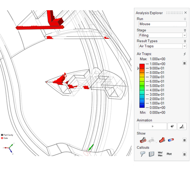
Detect potential problems—air traps, shrinkage, sink marks, warping, weld lines,
and more—during molding stages.Figure 1. Air traps discovered in an injection molding simulation
Optimized Five-Step Simulation Workflow
Five easy steps walk you through the simulation process.
Import CAD geometry and define the cavities for the parts you want to
create.
Define the material filling system for the injection molding including the
gates, runners, sprues, and injection points.
Define the mold, venting, coolers, and inserts for the part design.
Define the simulation parameters for the molding stages including filling,
packing, and cooling.
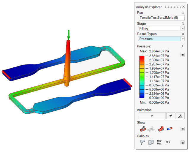
Run the simulation.Figure 2. Pressure results for the filling stage of an injection molding
simulation
Component Creation and Editing
The intuitive Inspire Mold tools let you create and edit components in your
model:
Parts: Designate your part cavity from existing CAD
geometry; easily make modifications through Inspire.
Runners: Define runners in your imported geometry or use
one-click options to automatically create full runner systems including gates,
sprues, and injection points. Use Hot Runner options to add controls and valve
gates to configure a variety of systems for maintaining ideal material
temperatures.
Materials: Import additional materials for your part
designs from the Altair Material Data Center.
Tooling: Define the part mold, cooler system and inserts
in your model geometry. Add venting for optimal part formation.