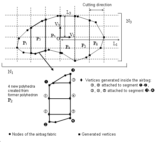
You may define an orthogonal frame (O,
V1,
V2, and
V3), a bounding-box of the
airbag fabric to be mesh defined by the lengths
(L1,
L2, and
L3) and the number of
cutting-step for each direction
(N1,
N2, and
N3).
The cutting width is then given by:(1)
Figure 1 shows a two-dimensional case of how
the airbag fabric is cut: Figure 1.
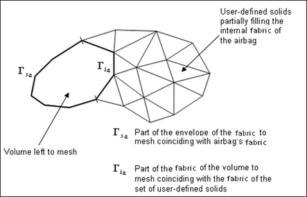
The automatic meshing procedure is also required if the set of user-defined solids
(Ibric) does not entirely fill the internal volume of the
airbag. Figure 2.
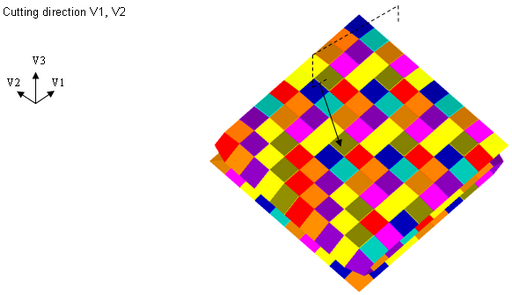
For example, in a case of a folded airbag with a right choice for the cutting
direction V1 and V2, meshing may be sufficient: Figure 3. Cutting Example 1 Figure 4. Cutting Example 2
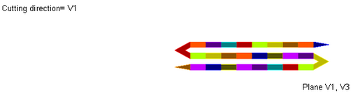
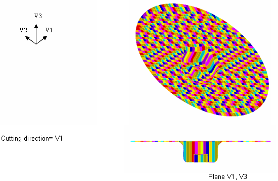
In cases where the injector is modeled with an initial rigid volume (canister), using
only two cutting direction (V1 and V3) gives a coarser mesh. Figure 5. Coarsher Mesh Around the Inflator
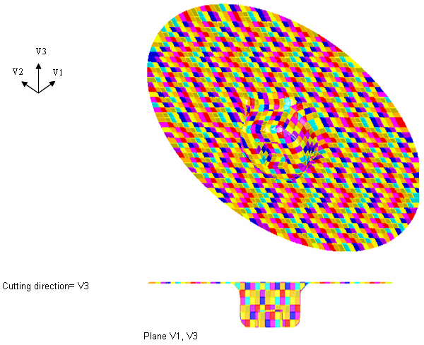
In this example, it may be greater to use the third cutting direction (V2) to reach
the following mesh: Figure 6. Meshing is Optimized Near the Injector Due to Cutting Direction
V3