OS-E: 0605 One Step Thermal Transient Stress Analysis
Demonstrates One Step Thermal Transient Stress Analysis using an exhaust manifold.
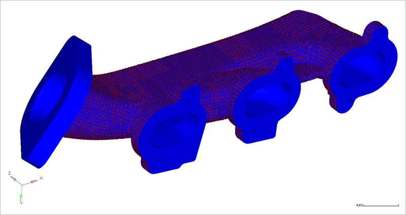
Figure 1. FE-Model
Model Description
An engine exhaust manifold with conjugate heat transfer and structural deformation, constructed of gray cast iron, initially at 300 K. The manifold outer surface has a convective heat transfer coefficient of h = 6 W/m2 K at 300 K. The four inlets to the manifold are held at 500 K with air as the fluid at 5 m/s.
Temperature history is available after linear transient heat transfer analysis. In order to apply temperatures at multiple time steps to a structural analysis, one step transient thermal stress analysis should be used. It provides displacement and stress history for the duration of transient heat transfer.
- FE Model
- Element Types
- CTETRA
- Young’s Modulus
- 1.38E11 PA
- Poisson's Ratio
- 0.283
- Initial Density
- 7817 Kg/m3
Stress vs Strain curve defined for MATS1 (for NLSTAT analysis only).
Results
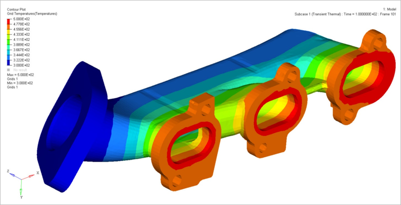
Figure 2. Grid Temperature Contour from Subcase 1
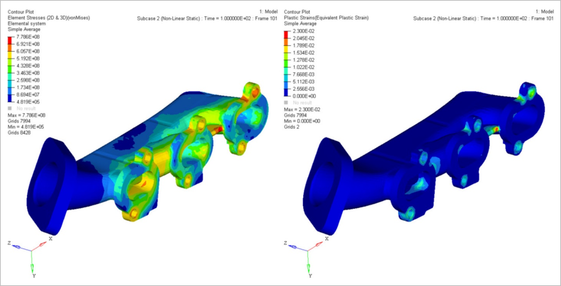
Figure 3. Element Stress and Plastic Strain form Subcase 2
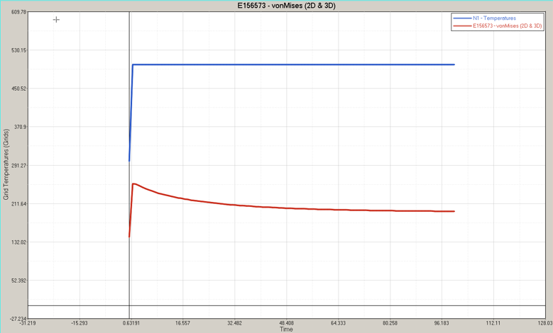
Figure 4. Stress and Temperature vs Time (Stress scaled to 1e-6)
Model Files
The model files used in this example include:
<install_directory>/hwsolvers/demos/optistruct/examples/OSTTS_MANIFOLD.fem