| 1. | Select the spin elems subpanel. |
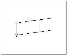
| 2. | Indicate the elements you want to spin: |
| • | Pick the elements on your model. |
or
| • | Click elems and choose from the extended entity selection menu. |
| 3. | Use the plane and vector collector to specify a plane. |
The elements are spun about the normal of the plane.
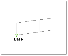
| 4. | Select base and select a base point. |
| 5. | Select angle = and specify an angle through which to spin the elements. |
| 6. | Select on spin = and enter the number of elements you want to generate along the path of the spin. |
| 7. | Click bias style: and select linear, exponential or bellcuve. |
| 8. | Click the data entry field after bias intensity = and enter the desired value. |
For more information on the biasing options, refer to the Element Biasing section in the Automatic Mesh Generation chapter of the User’s Manual.
| 10. | To generate the elements in the opposite direction, click spin-. |
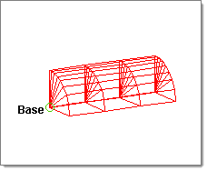
The elements in this illustration were created by using spin +, with a negative biasing value.
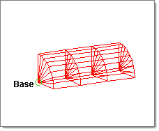
The elements in this illustration were created without element biasing.
Undo
Select reject immediately after you create the surface and/or mesh or elements. To reinstate the rejected entities, select spin+ or spin- again without changing any of the input data. The input nodes and/or lines or elements used to create the entities are restored provided that no data is selected after the surface and/or mesh or elements are created.
Comments
You can use a line segment.
The order in which the nodes are selected determines the connectivity of the mesh generated.
When one-dimensional elements are spun, two-dimensional elements are generated. When two-dimensional elements are spun, three-dimensional elements are generated. The spin operator ignores three-dimensional elements.


