| 1. | Click the upper entity selector switch and select lines. |
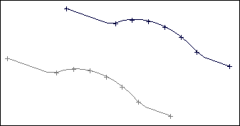
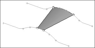
| 2. | Pick the first line where you want to create a surface. |
| 3. | Click the lowerentity selector switch and select lines. |
| 4. | Pick the second line where you want to create a surface. |
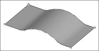
| 5. | Click the rightmost switch and select the desired mesh and surface option. |
For information regarding the meshing options, refer to the Automeshing section in the User’s Manual.
| 6. | Select auto reverse if you want to use the auto reverse feature. (See Comments.) |
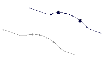
| 8. | To build a surface using line segments: |
Follow the same procedure as for using lines.
After you select the line, select the points on the line that define the segment where you want to create the surface.
| 9. | Select the second line segment you want to use. |
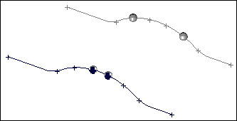
The surface is created between the defined line segments.
Undo
Click reject immediately after you create a surface and/or mesh. To re-create the entity, click create a second time without changing any of the input data. The input nodes and/or lines used to create the surface and/or mesh are restored provided no data is selected since it was created.
Comments
You can select all of the nodes for both sides of the surface and/or mesh using one entity selector. The number of nodes must be equal on both sides. HyperMesh then divides this list into two before creating the surface and/or mesh.
When elements are generated, the edges used to create this mesh can be ordered in different directions. This causes HyperMesh to create a mesh that crosses itself resembling a bow tie. The order of the edges is determined by the order in which the nodes were selected or the direction of the selected line(s). To prevent "bow ties" from occurring, the default auto reverse parameter is provided to insure that elements are generated with a similar order on each side of the mesh. Toggle auto reverse to no reverse to disable this feature.
It is also possible to select a series of lines to be used in creating one side or the other of the surface and/or mesh.


