This tutorial shows you how to set up a hot isothermal forging simulation of a T-Joint using the DEFORM solver.
Before you get started, you should be familiar with basic HyperMesh functionality including meshing, geometry cleanup and mesh editing. For help with these topics, see HyperMesh tutorials.
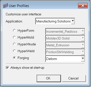
Step 1: Loading the Forging User Profile
| 1. | To load the Forging user profile that directly interfaces with the DEFORM solver, launch HyperMesh. |
| 2. | On the User Profiles dialog that appears, for Application, select Manufacturing Solutions, Forging and Deform as you see in the following figure: |
Step 2: Importing Billet and Tooling Geometries
| 1. | On the Utility Menu, click the CAD macro. |
| 2. | From the Files panel, change the option for the file type to IGES. |
| 3. | Click import… and browse to load the file, Teebillet.iges. |
Note: The model files for this tutorial are located in the file mfs-1.zip in the subdirectory \forging\. See Accessing Model Files.
| 5. | On the Utility Menu, click the FE macro. |
| 6. | From the Files panel, change the option for the file type to STL. |
| 7. | Repeat step 2 and retrieve the files Teetop.stl and Teebottom.stl one after the other. |
| 9. | On the Utility Menu, click Comps to create three separate components named billet, top_die and bottom_die with the card image PART and suitable colors. |
| 11. | From the Organize panel, move the STL mesh and billet surface to the corresponding components. |
Step 3: Meshing the Billet
| 1. | In the Model Browser, right-click the component billet and select Make Current. |
| 2. | On the Utility Menu, click the Tetramesh macro. |
| 3. | On the Tetramesh panel, select the volume tetra radio button. |
| 4. | Under the enclosed volume collector, select surfs. |
| 5. | Do the following: Check use curvature & use proximity; Click the billet surface from the graphics area; Enter the element size as 0.09, min element size as 0.09 and then click the mesh button. |
| 6. | Click return to accept the mesh. |
Step 4: Creating Material with Flow Stress Data for the Billet
| 1. | From the Utility Menu, click the Materials macro. |
| 2. | From the Collectors panel, in the name field, enter steel. |
| 3. | Click the Card image button and select MAT. |
| 4. | Click create, and then return. |
| 5. | From the Utility Menu, click the Flow Stress macro. |
| 6. | From the Materials Flow Stress data dialog, for materials, select steel. |
| 7. | For Type, select option 2. |
| 8. | For Nstrain, Nsrate and Ntemp, enter the values 3, 4, and 2 respectively. |
| 9. | Locate the Curves field, and then click … and browse to the file mat_sample.dat. |
| 10. | Click Apply. Note that mat_sample.dat contains the flow stress data at given strains, strain rates and temperatures. |
Step 5: Assigning Billet Material
| 1. | From the Utility Menu, click the Comps macro. |
| 2. | Select the update radio button. |
| 3. | For Comps collector, select billet and then click return. |
| 4. | Click the Card image button, and then select PART. |
| 5. | Click the materials button, and then select steel. |
| 6. | Click the update/edit button, and then select billet. |
| 7. | From the card image, click OBJTYP and then select option 2. |
| 8. | Click Mesh>Check>Component>Mass/area calculation. |
| 9. | Click the yellow Comps button, and then select billet |
| 11. | Click Calculate, and then copy the value from the Volume text field. |
| 12. | Repeat steps 1-6 to get the billet attributes. Enter that value from (10) under TRGVOL. |
Note: TRGVOL is the target volume and that this value is used to eliminate the volume loss during remeshing.
Step 6: Assigning a Temperature for the Billet
Note: For cold forging, this step is not necessary.
| 1. | From the main panel area, click the Temperatures panel. |
| 2. | For Comps collector, select billet and click return. |
| 3. | Under value, type 1900 as the temperature of the billet. |
Step 7: Defining Contact Between the Billet and Dies
| 1. | From the Utility Menu, click the Contacts macro to enter the Interfaces panel. |
| 2. | Ensure that the Create radio button is active. In the name field, enter billet_top. |
| 3. | Click type and select CONTACT. |
| 4. | Under the creation method ensure that the option is Card image and the corresponding field displays CONTACT. |
| 5. | Click the interface color and select a suitable color. |
| 7. | Select the card image radio button. |
| 8. | Click edit. Enter the value of 0.25 for FRCFAC inside the card image. |
| 10. | Select the add radio button. Double-click the name to display the billet_top die. |
| 11. | Click the yellow Comps button for master, and then select the top die. Click return. Click the Update button next to master. |
| 12. | Click the yellow Comps button for Slave, and then select the billet. Click return. Click the Update button next to Slave. |
| 13. | Repeat steps 1 - 12 and create a contact for the billet and the bottom die with name billet_bot. |
| 14. | Repeat steps 1 - 12 and create a contact named billet_billet for the billet’s contact with itself. |
Note: Self contact for the billet is used to detect a possible fold in the component during the forging process.
Step 8: Positioning the Billet and Dies
| 1. | From the Utility Menu, click the Tool Position macro. |
| 2. | Select the bottom_die as the reference part and the billet as the translation part. |
| 3. | Select Z- as the direction of approach. |
| 4. | Click Apply. This will move the billet down very close to the bottom_die. |
| 5. | Repeat steps 1 - 4 to position the top_die with respect to the billet. |
Note: Depending on the original location and orientation of the billet with respect to the dies, you may need to use additional tools such as Translate and Rotate from the pull-down menu to correctly position the billet with respect to the tooling. The following figures show the correct positioning for this model:
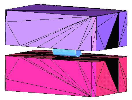
Positioned cylindrical billet with respect to top and bottom die
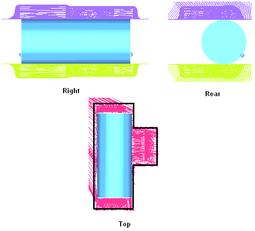
Different views after positioning
Step 9: Setting Up Motion for the Top Die
| 1. | From the Utility Menu, click Tool Motion. |
| 2. | From the Tool Motion dialog, select Top_Die for the Moving tool. |
| 3. | For Moving Control type, select speed controlled. |
| 4. | Enter 0 for unit vectors in X and Y direction and –1 for Z direction. |
| 5. | Enter 1.1 for Max Stroke, which is the same as SMAX. |
Note: The max stroke is the amount by which the top die needs to move to complete the forging. Carefully select an appropriate gap for the flash.
Step 10: Defining Control Cards
| 1. | From the main panel, click Control cards. |
| 2. | Click Process Definition. Type in SIM1 in the TITLE text field. |
| 3. | Scroll down to find SIMNAME. Type in T-joint in the text field. Click return. |
| 4. | Click Stopping Stepping control card to check the following default values: |
DSMAX = 1% of SMAX
NSTEP = 200
STPINC = 10
Step 11: Saving and Exporting the Deck for the DEFORM Solver
| 1. | From the Utility Menu, click Save to get to the Files panel. |
| 2. | From the Files panel, save the model file as T_joint.hm. |
| 3. | From the Utility Menu, click Export. |
| 4. | In the File name field, enter T_Joint.key. |


