|
»Click here to display Table of Contents«
|

Model Data |

|

|

|

|
|
Model Data |
|
|
|

|
|
»Click here to display Table of Contents«
|
Model Data |
|
|
|
|
|
Model Data |
|
|
|
|
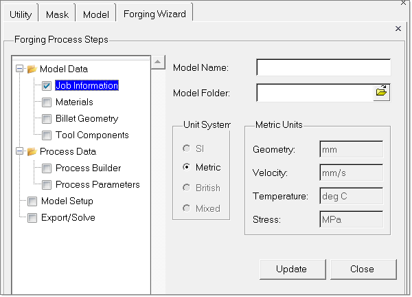
| • | Allows you to specify model name and folder |
| • | The unit system for the model can be selected. Currently only Metric system is available, but other unit systems will be made available. |
| • | The units used for Geometry, Velocity, Temperature and Stress are exported as parameters in *.frg file. |
| • | Material for the billet can be selected from the available workpiece material data base |
| • | Material for the tool components can be selected from the available tool material database |
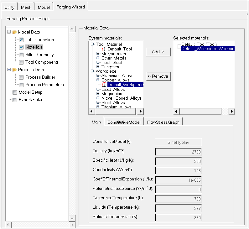
| • | Once you select the materials for tool and workpiece, the properties of those materials are exported as data packets in *.grf file as shown below. In addition, these materials are assigned to the components accordingly. |
Tool Default_Tool { Density = 2260 SpecificHeat = 896 XConductivity = 198 YConductivity = 198 ZConductivity = 198 VolumetricHeatSource = 700 YoungModulus = 2.00000000000E+10 PoissonRatio = 3.50000000000E-01 } Workpiece Default_Workpiece { ConstitutiveModel = "SineHypInv" Density = 2700 SpecificHeat = 900 Conductivity = 198 CoeffOfThermalExpansion = 1.00000000000E-05 VolumetricHeatSource = 0 ReferenceTemperature = 700 LiquidusTemperature = 927 SolidusTemperature = 889 YoungModulus = 4.00000000000E+10 PoissonRatio = 3.50000000000E-01 StressExponent = 5.38500000000E+00 StrainRateOffset = 1.00000000000E-04 ActivationEnergy = 141550 ReciprocalStrainFactor = 5.91052000000E+09 UniversalGasConstant = 8.31400000000E+00 Alpha = 4.00000000000E-08 }
BEGIN MATASSIGN USE Default_Workpiece FOR Billet_3D USE Default_Tool FOR LeftClamp_3D USE Default_Tool FOR RightClamp_3D USE Default_Tool FOR Tool1_Punch1_3D USE Default_Tool FOR Tool1_Punch2_3D USE Default_Tool FOR Tool1_Punch3_3D USE Default_Tool FOR Tool1_Punch4_3D END |
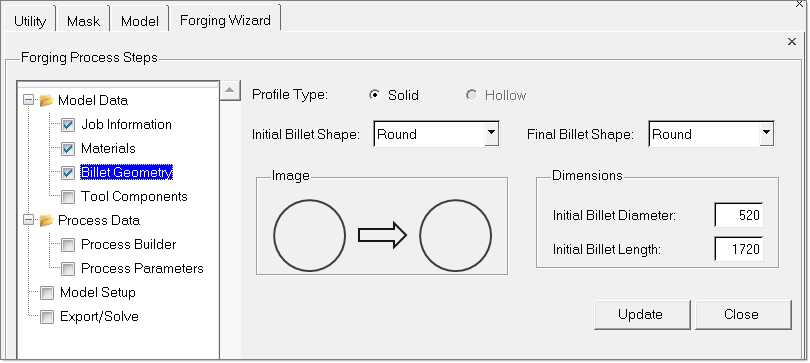
| • | You can specify the initial and final shape of the billet. |
| • | You can specify the initial dimensions of the billet before the start of forging process. |
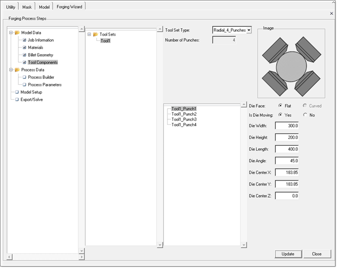
In this step, you can specify tool set information.
At present radial forging with 4 punches and press forging with a punch and anvil are supported. Once the tool set type is selected, for each tool component (punch/anvil), you can specify the geometry information such as width, height, length, orientation angle and face center coordinates.
All these toolset and tool component details are exported to a *.grf file as explained below.
Note: You should verify that all punches that belong to one tool set have same width, length and height.
Name |
Description |
Die Face |
Type of die face. Should be either “Flat” or “Curved”. Only “Flat” face dies are supported at present. |
Is Die Moving |
This parameter distinguishes whether a die is “Punch” or “Anvil”. |
Die Width |
Width of the die in transverse direction |
Die Height |
Height of the die |
Die Length |
Length of the die in billet orientation direction |
Die Angle |
Describes the radial orientation of the die with respect to billet |
Die Center X, Y, Z |
Coordinates of the Die face center. These are automatically computed given the die angle and billet initial diameter. |
All the specified die parameters of each tool component in the tool set are exported as a DieData data packet in *.grf file. Sample data packet DieData is shown below.
| • | Here, DieData is the keyword to specify the data packet is a DieData type. |
DieData Tool1_Punch1_Data { DieType = "Punch" DieFace = "Flat" Width = 300.0 Length = 400.0 Center = 183.85 183.85 0.0 Angle = 45.0 DieElemSet = "Tool1_Punch1_3D" } |
| • | Tool1_Punch1_Data is the name of the die component “Tool1_Punch1” appended with the string “_Data” |
| • | DieElemSet - represents the 3D component |
| • | Similarly the *.grf file contains data packets for all the die components, Tool1_Punch2, Tool1_Punch3 and Tool1_Punch4. |
The number of die components and names of the die components associated with this tool set are also exported as a ToolSet data packet. In addition ToolSet data packet also contains the information about Clamp components that hold the workpiece during forging process. Samples of these data packets are shown below.
ToolSet Tool1 { NumDieComponents = 4 DieComponentNames = "Tool1_Punch1_Data" "Tool1_Punch2_Data" "Tool1_Punch3_Data" "Tool1_Punch4_Data" NumClampComponents = 2 ClampComponentNames = "LeftClampData" "RightClampData" } |
Here, the keyword ToolSet indicates that the data packet is of ToolSet type and “Tool1” refers to the name of the tool set.