|
»Click here to display Table of Contents«
|

Context-Sensitive Menu |

|

|

|

|
|
Context-Sensitive Menu |
|
|
|

|
|
»Click here to display Table of Contents«
|
Context-Sensitive Menu |
|
|
|
|
|
Context-Sensitive Menu |
|
|
|
|
From the Model browser, you can access the following context menu options by right-clicking on a folder, entity, or in white space. These context menus will appear only where they are applicable hence making them smart and compact.
Option |
Available for: |
Description |
||||||||||||
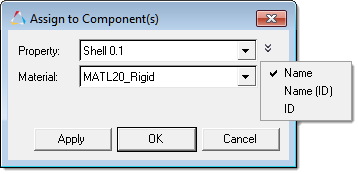
Assign |
Components |
Opens a dialog from which you can assign properties and materials to the selected components. You can view properties by name, name and ID, or ID only.
|
||||||||||||
Card Edit |
All |
You can edit any single item's card. You can edit multiple items provided that they use identical card images. This option displays the card image of the chosen entity for the current solver template; if a template is not loaded or if the entity does not have any card images associated with the loaded template, an error message displays in the status bar. |
||||||||||||
Collapse |
All folders |
Closes the selected folder(s) and its children folders (if any), so that only the selected folder displays. |
||||||||||||
Collapse All |
White space |
Closes all of the folders in the tree structure, so that only the top-most level of items displays. |
||||||||||||
Configure Browser |
All |
Opens the Model browser’s Browser Configuration window where you can specify the entities the browser displays in the tree as well as the columns the browser displays. |
||||||||||||
Create |
White space and the respective folder; user profile valid entity from the list: Assembly, Beam Section Collector, Block, Box, Component, ConstrainedExtraNode, ConstrainedRigidBody, Contact, Contact Surface, Control Volume, Cross Section, Feature, Field, Group, Include File, Laminate, Load Collector, Load Step, Material, Multibody, Output Block, Parameter, Plot, Ply, Property, Region, Rigid Wall, Sensor, Set, System Collector, Transformation, Vector Collector, View, Accelerometer, Positions (Abaqus) |
Opens the Create dialog, from which you can define and create a new entity. If you are creating a new entity in the Altair Radioss, Altair OptiStruct, Nastran, LS-DYNA, Abaqus, ANSYS, PAM-CRASH, Permas, Samcef, and Exodus user profiles, HyperMesh creates the new entity and opens it in the Entity Editor. Use the Entity Editor to modify entity data. When you create a new Assembly or Include File, HyperMesh assigns it a unique, generic name and adds it to the Model browser. When you create a View, HyperMesh saves the current model’s graphics settings in the browser. Saved views include all of the visible effects of settings such as masks, zoom/pan, X/Y/Z orientation, and whether or not any given component's FE or Geometry is displayed. You can save multiple views (named view1, view2, and so on), and then switch back and forth between them by selecting each view from the browser. |
||||||||||||
Delete |
All except the top-level of Assemblies |
Deletes the selected entities. Most items can be deleted.
|
||||||||||||
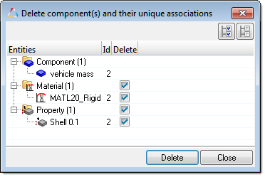
Delete Advanced |
Components in the Abaqus, Altair OptiStruct, Nastran, LS-DYNA user profile. |
Displays a comprehensive preview of the entities uniquely related to the selected component that can also be deleted.
|
||||||||||||
Drape |
Ply |
Access to the Drape Estimator and Laminate Tool.
|
||||||||||||
Duplicate |
User profile valid entity from the list: Assembly, Beam Section Collector, Block, Box, Component, ConstrainedExtraNode, ConstrainedRigidBody, Contact, Contact Surface, Control Volume, Cross Section, Feature, Field, Group, Include File, Laminate, Load Collector, Load Step, Material, Multibody, Output Block, Parameter, Plot, Ply, Property, Region, Rigid Wall, Sensor, Set, System Collector, Transformation, Vector Collector, View, Accelerometer, Position (Abaqus) |
Duplicates a selected entity and opens it in the Create dialog. If you are duplicating an entity in the Altair Radioss, Altair OptiStruct, Nastran, LS-DYNA, Abaqus, ANSYS, PAM-CRASH, Permas, Samcef and Exodus user profiles, HyperMesh duplicates the selected entity and then opens it in the Entity Editor. Use the Entity Editor to modify entity data.
|
||||||||||||
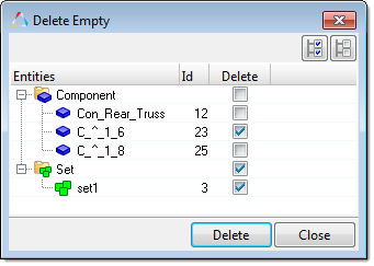
Empty |
Assembly, Beam Section Collector, Component, Control Volume (Altair OptiStruct), Group, Load Collector, Load Step, Multibody, Output Block, Set, System Collector, Vector Collector, Accelerometer, Position(Abaqus), Ply, Feature, Field, Rigion, Include file, Cross-Section, Plot, ConstrainedRigidBody. |
Preview and delete empty collectors. This operation can be performed on several entity types at the same time. To append entity types to the selection, left-click while pressing CTRL.
|
||||||||||||
Expand |
All folders |
Opens the selected folders and children in the tree structure, exposing every item nested in the selected folder. |
||||||||||||
Expand All |
White space |
Opens all of the folders in the entire tree structure, exposing every item nested at every level. |
||||||||||||
Export All Includes |
Model Browser Include View only |
Exports all of the includes with their corresponding content, including the Master model. |
||||||||||||
Export All Self Contained |
Model Browser Include View only |
Exports all of the model (master model and includes) as self-contained files, ensuring that each exported file contains all of the nodes and systems that are referenced by entities within the given include, as described above (see Export Self Contained option).
This option is only available in the Altair OptiStruct, Nastran, and Abaqus user profiles. |
||||||||||||
Export CSV |
Model Browser Model View only, and Beam Section Collector folder |
Exports a CVS file of all beam section names, each part within the section, corresponding thickness and vertex numbers, and positions. Note: Only available for shell sections. |
||||||||||||
Export an Include |
Model Browser Include View only |
Exports the contents of the selected include into the chosen file name. |
||||||||||||
Export Self Contained |
Model Browser Include View only |
Exports the contents of the selected include into the chosen file name, and ensures that the exported file contains all of the nodes and systems that are referenced by entities within the same include, even if such nodes and systems belong to different includes. Because self-contained includes contain all of the nodes and systems that are used by entities within it, they can always be imported into HyperMesh on their own without requiring the rest of the model. This option is only available in the Altair OptiStruct, Nastran, and Abaqus user profiles. |
||||||||||||
Hide |
All except Beam Section, Curve, and Optimization Entities |
Turns off the entity in the graphics area. This selection affects each item’s local display control, that is, will make the icon become ghosted indicating the display state is off. You can also use this on the entire folder. In such cases, this hides all of the items within that folder (for example all components, and so on). |
||||||||||||
Import CSV |
Model Browser Model View only, and Beam Section Collector folder |
Imports new shell beam sections from a HyperBeam CSV file, without having to use a .hm file. Note: Only available for shell sections. |
||||||||||||
Include File Options |
Model Browser Include View only |
These let you set the options for a selected include. The available options are:
|
||||||||||||
Include XRef |
Include file |
Any single item or multiple items can be selected. This option opens a new References browser that displays the relationship of the selected include to other includes in the model in a hierarchical tree structure. |
||||||||||||
Isolate Only |
All except Beam Section, Curve, and Optimization Entities |
Isolate Only works like Isolate, except that it affects all entities regardless of type. This option turns off the display of all entities that are not selected. |
||||||||||||
Isolate |
All except Beam Section, Curve, and Optimization Entities |
Isolate works locally within a specific entity type; for example, if component(s) are isolated then all display states of other entities, such as load collectors, are unaffected. Isolate displays only the selected entities, and turns off all other entities of the same type. |
||||||||||||
Make Current |
BeamSection Collector, Components, Load Collector, Multibody |
Using the pop-up menu, you can make any listed entities current. The current collector status is indicated in bold. Any new components, loads, beam sections or multibodies are created within the respective current collector. |
||||||||||||
Move To Include |
Component |
Opens the Move To Include dialog, from which you can create a self containing include out of selected components inside of an include. Available in the LS-DYNA and Altair Radioss user profile. |
||||||||||||
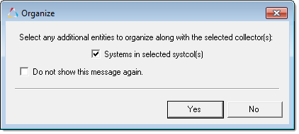
Organize |
All |
Organizes the selected entities into the current include. This option is only enabled in the Include view. The Organize dialog opens when system collectors, vector collectors, load collectors, beamsection collectors, groups, multibodies, and components are being organized into the current include. By default, any additional entities (nodes, elements, systems, vectors, loads and equations, or beamsections) will be moved along with selected parent collectors. If there are entities you do not want to organize along with the selected collector(s), clear their corresponding check box.
|
||||||||||||
Organize Include |
Include Files (Include View only) |
Opens the Organize Include dialog, from which you can move selected entities into a new or existing include file. Available only in the LS-DYNA and Altair Radioss user profile. |
||||||||||||
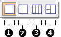
Part Xref |
Include Files (Include View only) |
Opens the Part References tab, from which you can review all of the part assemblies and parts in an Include file in a hierarchical view or in a flat list. Within the Part References tab there are two predefined view modes: Hierarchy view and Flat view. The different view modes are located in the top, left corner of the tab.
|
||||||||||||
Realize |
Plies |
If ply contours are defined by lines, the realize algorithm will identify elements of an underlying mesh. If an element centroid lies within the ply shape defined by lines, it is added to the particular ply. You can manually define plies on lines in Altair HyperMesh or import them from a Catia Composite Parts Design (CPD) file. Along with this, if a ply has its shape defined in triangulation mesh (in the case of fibersim imported data), that data will be used in projecting on the actual mesh. Three realization/conversion methods are available:
Advanced options: Three options are available for the search criteria:
Input Sample Point: Judging whether elements reside inside of a ply boundary is sometimes challenging, especially on a curved surface. Using correct sample points (or nodes) to indicate if the elements are inside helps ply realization. You should use this method for each ply, not for all of the plies. It is recommended to use ply realization for all the plies, and then inspect each ply to make sure it is correct. If the ply realization is wrong, correct that ply only using sample points or interactive nodes. You can either import the core sample .csv file, or interactively pick nodes for a ply. |
||||||||||||
Laminates |
A laminate can also be realized. In this step, you create and assign properties to elements to translate the ply-based composite's definition into a zone-based one. A template composites property has to be assigned to the elements involved in the composites definition prior to this step. The algorithm copies all settings from this property to the newly generated ones. Each zone of elements with a unique set of plies receives its own property. If there is drape data available on every ply (such as fibersim drape data) then thickness and fiber orientation corrections are applied to each property layer/ply automatically. Currently Laminate Realize with drape data results into one property per element. To open the Laminate Realize dialog, right-click on a laminate in the Model browser, and then select Realize. |
|||||||||||||
Fields |
Field realization creates pressures and temperature loads, and maps properties IDs. In order to map the spatially varying values stored in a field entity to the element and node data of the new target mesh you must realize the field entity. Define field realization settings in the Field Realization dialog, which opens when you right-click on a field in the Model browser and select Realize from the context menu. |
|||||||||||||
Remove |
Components |
Removes the component from an assembly if the component is referenced in more than one assembly.
|
||||||||||||
Rename |
All |
You can rename any item in the name text field, but the new name must be unique. All instances of the renamed item update automatically. You can cancel the rename operation by pressing ESC. The high-level entity folders are non-editable, but you can rename folders containing the assembly hierarchy. |
||||||||||||
Replace |
Component |
Opens the Part Replace dialog, from which you can quickly replace a part with either an existing part in your model or a part from an external file. This option is only available in the LS-DYNA user profile. |
||||||||||||
Review |
Assemblies, Beamsection collectors, Beamsection, Blocks, Bodies, Boxes, Components, Configuration, Constrained extra nodes, Constrained rigid bodies, Constraints, Contact surfaces, Control volumes, Crosssections, Design variables, Design variable links, Design Objective Reference, Design Variable Property Relationship, Elements, Groups, Joints, Laminates, Load collectors, Loads, Loadsteps, Materials, Mechanisms, Objectives, Optimization constraints, Optimization responses, Output blocks, Part, Part Assembly, Part Set, Plies, Properties, Regions, Seatbelts, Sensors, Sets, System collectors, Systems, Vector collectors, Vectors. |
Invokes Review mode, which displays selected entities irrespective of their display state, masked, active state (Entity State browser), but not outside of the spherical clipping (if enabled). |
||||||||||||
Show |
All except Beam Section, Curve, and Optimization Entities |
Displays the item in the graphics area. The item's icon changes to bold indicating that the display state is on. You can use the Show option on a folder to display all items within a folder (for example, all components). |
||||||||||||
Unrealize |
Laminates |
Unassigns properties previously assigned to elements through the Realize function. These properties are not deleted, but merely disassociated from the elements. |
||||||||||||
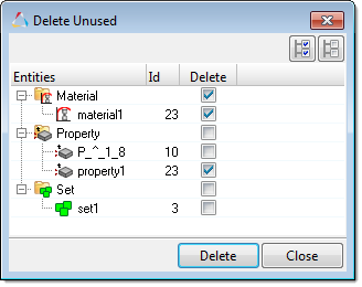
Unused |
System, Property, Curve, Material, Parameter, Block, Box, Encriptions, Features, Field, Rigion, Contact Surf, Ply, Include file, Set |
Preview and delete unused property collectors, material collectors, curves, and so on. This operation can be performed on several entity types at the same time. To append entity types to the selection, left-click while pressing CTRL.
|
||||||||||||
XRef Entities |
Assembly, Beam Section Collector, Block, Box, Card, Component, ConstrainedExtraNode, Contact, Contact Surface, Control Volume, Cross Section, Curve, Field, Group, Include File, Laminate, Load Collector, Load Step, Material, Multibody, Output Block, Parameter, Plot, Ply, Property, Region, Rigid Wall, Sensor, Set, System Collector, Table, Transformation, Vector Collector |
Any single item or multiple items can be selected. Opens the References browser and displays the relationship of the selected entities to other entities in the model in a hierarchical tree structure. |