Manufacturing Solutions includes an interface for friction stir welding simulation. This interface provides all the tools to create data for friction stir welding and launch the solver. The FSW interface uses the HyperXtrude solver to obtain the solution, therefore you will find a lot of similarity between the HyperXtrude and FSW interface. In addition, it is possible to use the FSW interface to create HyperWeld data decks.
Data generated for HyperWeld analysis is organized into two files: GRF and TCL files. The GRF file contains the mesh, material data, boundary conditions, and other special data. The TCL file contains commands to set process parameters and control the solver operations. These commands are in TCL language. In order to make this process of generating data files simple and efficient, the following features are embedded in the interface.
The HyperMesh Window
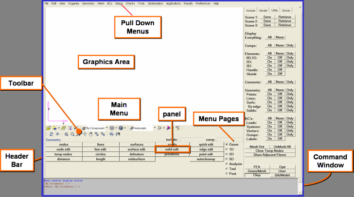
HyperMesh main window
There are several main areas in the HyperMesh window:
Area
|
Description
|
Title bar
|
The bar across the top of the interface is the title bar. It contains the version of HyperMesh that you are running and the name of the file you are working on.
|
Graphics area
|
The graphics area under the title bar is the display area for your model. You can interact with the model in three-dimensional space, in real time. In addition to viewing the model, entities can be selected interactively from the graphics area.
|
Menu bar
|
Located just under the title bar. Like the pull-down menus in many graphical user interface applications, these menus "drop down" a list of options when clicked. Use these options to access different areas of HyperMesh functionality.
|
Toolbar
|
Located just under the graphics area, these buttons provide quick access to commonly-used functions, such as changing display options.
|
Command Window
|
You can type HyperMesh commands directly into this text box and execute them instead of using the HyperMesh Graphical User Interface.
|
Utility Menu
|
This area contains five pages of macros that perform various functions. The Disp macro page is active and is shaded to signify this. The Disp page macros control how a model displays in the graphics area.
The other macro pages available are QA (contains element checking macros), Mesh (contains macros associated with creating and editing meshes), User (contains macros you create), and Geom (contains macros related to working with a model’s geometry).
The content of the Utility Menu changes based upon the selected user profile.
|
Header bar
|
The header bar separates the graphics area from the panel area. The left end of the header bar displays your current location. At this time, you will see geometry displayed. The three fields on the right side of the header bar display the active user profile, current component collector and current load collector. The latter two fields are blank.
As you work in HyperMesh, any warning or error messages also display in the header bar. Warning messages appear in green and error messages appear in red.
The quit button on the rightmost end of the Header bar ends the HyperMesh session. When you select quit, if changes have not been saved a save file information confirmation message appears so you can save your changes before HyperMesh closes down.
Hint You can hold the left mouse button down on top of a panel to see a description for it in the Header bar.
|
Page menu
|
The Page menu allows you to select different sets of functions.
The Geom page contains functions having to do with the creation and editing of geometry.
The 1D, 2D, and 3D pages contain element creation and editing tools grouped according to element type.
The Analysis page contains functions to set up the analysis problem and define the boundary conditions.
The Tool page contains miscellaneous tools and model checking functions.
The Post page contains post-processing functions.
|
Panel menu
|
The Panel menu displays for each page the functions available on that page. You access those functions by clicking on the button corresponding to the function you wish to use.
|
Friction Stir Welding User Profile
HyperMesh is designed to accommodate many different FE solvers. As a result, some panels may be too general for FSW. By selecting the FSW profile, you can work with pre-defined panels that are more specific.
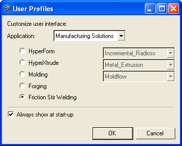
To load the HyperWeld user profile:
| 2. | On the Preferences menu, click User Profiles. |
| 3. | For Application, select Manufacturing Solutions. |
| 4. | Select Friction Stir Welding. |
Friction Stir Welding Utility Menu
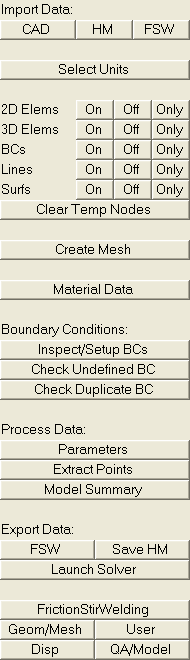
The FSW Utility Menu lists options to import models into HyperMesh, create weld mesh, select and assign material properties, define and apply boundary conditions, define process conditions, and export data files to HyperXtrude.
Buttons in the macro menu fall into two categories:
| • | Shortcuts to native HyperMesh panels |
Import Data
|
CAD
|
Imports CAD drawing.
|
HM
|
Imports an HyperMesh file.
|
FSW
|
Imports a HyperWeld data deck, including both the GRF and TCL files.
|
Select Units
|
Allows you to set the units used in modeling the problem.
|
2D Elems
|
Allows you to control 2d element display.
|
3D Elems
|
Allows you to control 3d element display.
|
Loads
|
Allows you to control display of Loads.
|
Lines
|
Allows you to control display of Lines.
|
Surfs
|
Allows you to control display of Surfaces.
|
Material Data
|
This macro button allows you to select materials from material database and assign material properties to different components. You can also view Viscosity/Flow stress graph for a material.
|
Process Data
|
These macro buttons allow you to define boundary conditions, solution monitoring points, job control parameters, and model summary.
|
Boundary Conditions
|
Inspect/Setup BCs
|
Allows you to view and assign boundary conditions on element faces.
|
Check Undefined BC
|
Identifies external faces without loads.
|
Check Duplicate BC
|
Identifies duplicate loads.
|
Process Data
|
Parameters
|
Specifies process control parameters.
|
Extract Points
|
Defines solution-monitoring points. The HyperXtrude solver prints detailed solution history at these points.
|
Model Summary
|
Inspects summary data such as number of elements and loads.
|
Export Data
|
FSW
|
Saves an FSW data deck and start the HX solver.
|
HM
|
Allows you to save the data in HyperMesh format.
|
Launch Solver
|
Allows you to Launch HX Solver using the current model, using Data deck or using a restart file.
|
Return to Friction Stir Welding Tutorials


