|
»Click here to display Table of Contents«
|

Edge Edit panel |

|

|

|

|
|
Edge Edit panel |
|
|

|

|
|
»Click here to display Table of Contents«
|
Edge Edit panel |
|
|
|
|
|
Edge Edit panel |
|
|
|
|
User Profiles: |
Incremental_RADIOSS Incremental_LS-DYNA RADIOSS One Step Die Module |
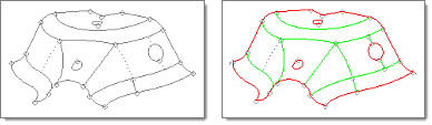
The edge topology helps control the mesh generation for the surfaces and surface boundaries when using the surface automesher. Edges can have one of three states, each of which has a specific color in the rendering graphics:
| • | Free edges (red) indicate that a surface edge is not connected to any other surface edge. The mesh generated across a free edge boundary will not be connected. |
| • | Shared edges (green) indicate a boundary between connected surfaces (sometimes referred to as “stitched together”). The mesh across a shared edge will place nodes along the surface edge, and such nodes will be common to the elements on each side of the boundary. Shared edges are further classified as manifold (exactly two surfaces meeting at a common edge) or non-manifold (yellow), where more than two surfaces meet at a common edge. For the sake of simplicity, shared manifold edges are simply referred to as “shared” while shared non-manifold edges are referred to as “non-manifold”. |
| • | The third edge topology state is suppressed (rendered in blue), where a manifold shared edge will be disregarded by the meshing process, in effect making a single larger surface out of two individual surfaces. |
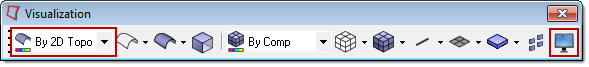
When entering any panel where the primary function is editing geometry, the surface topology display mode is activated by default. In this mode, the surface edges are colored according to their topology state. The default color assignments are red for free edges, green for shared edges, yellow for non-manifold edges and a blue dotted line for suppressed edges. The color assignment can be changed using the visualization options button, and the surface topology display mode can be set at any time using the geometry display mode button. Both of these buttons reside in the visualization toolbar.
Each type of edit option for edges is arranged into its own subpanel. You can move freely between subpanels--your work on one subpanel will not be lost if you switch to a different subpanel, then return. However, similar settings will not be shared between subpanels, so for example changing the cleanup tolerance in one subpanel does not change it in any of the others. In some cases, changes will be reflected immediately in your model as you select edges; in others, one or more green command buttons on the right edge of the subpanel can be used to execute the function once all criteria have been specified.
| • | Set the panel mode by selecting the subpanel appropriate to the type of edit you wish to perform. |
| • | In the subpanel, choose specific edges, or surfaces whose edges you wish to edit. |
| • | In the subpanel, choose input criteria to limit the edges that will be edited, or use the default values. These criteria act as a filter so that you can select multiple edges or surfaces but only edit edges that meet certain qualifications, such as proximity to one another or length restrictions. |
Use the interactive image below to see the various options on each subpanel. Mouse over each element to see a brief description. Click a subpanel to reveal the selection criteria that it contains. |
The Edge Edit panel contains the following subpanels and command buttons:
This subpanel toggles edges from one state to another. The topology state can be advanced from free to shared to suppressed by clicking with the left mouse button. Conversely, the state can be regressed from suppressed to shared to free by using the right mouse button. Exactly what state an edge takes on depends on its current state. Adjacent free edges can be advanced to shared edges with the left mouse button, provided the two edges are within the same space based on the cleanup tolerance setting. The tolerance is used to create a search sphere around the point that is clicked. If another free edge is found, it is considered for a pairing. Any paired edges are checked for an appropriate match along their length based on the cleanup tolerance. The shared edge resulting from this toggle operation will be at the location of the free edge that is clicked. Left-clicking a shared edge will result in a suppressed edge. Left clicking a non-manifold edge has no effect, since the mesh must have nodes along such a boundary. Right-clicking a suppressed edge reverts that edge to the shared state. Right-clicking a shared edge releases the edge to the free state. In general, left-clicking reduces the number of edges, while right-clicking increases the number of edges:
Panel Inputs
|
Use this subpanel to suppress or unsuppress edges. Suppressed edges are treated as if they did not exist when meshed using the surface automesher, and their corresponding surfaces and resulting mesh will be continuous. However, the edges still remain in the database, and can be unsuppressed again if necessary. Panel Inputs
|
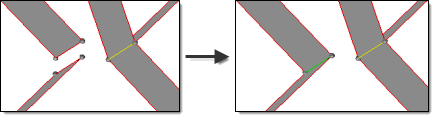
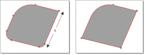
Use this subpanel to move one edge line to the same edge as another, effectively combining the two edges into a shared edge at the location of one of the original edges. This functionality provides additional control over the toggle function. Individual selections are made for the line to move and the line to retain. The resulting shared edge will be at the location of the line selected as retained. The cleanup tolerance setting in this panel defines the maximum distance between the selected lines.
Panel Inputs
|
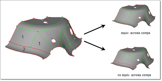
Use this subpanel to search for free edges and combine them with a matching edge within the cleanup tolerance. The surfs selector allows selection of surfaces to check using any of the extended selection options. Selected edges that meet other specified criteria will be equivalenced even if they belong to different components. In the example below, surfaces are selected from components 1 and 2.
Panel Inputs
|
Use this subpanel to remove previously created split-lines; that is, lines that have been added to split one surface into multiple surfaces. This function can also be used to remove closed-edge loops, such as holes in a surface.
Panel Inputs
|
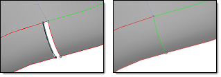
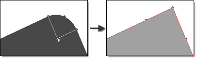
Use this panel to remove fillets from surface edges. You can replace fillets in one of two ways:
Both options display on this subpanel, but are mutually exclusive: you may use one or the other, but you cannot use both on the same fillet. You can, of course, use both types in the same model, just not on the same fillet. The option to remove fillets can be performed on as many fillets as you wish; all fillets in the model meeting the criteria you specify will be located and selected. Replacing a fillet with a trim-intersection corner, however, is a manual process that can only be performed on one fillet at a time. The Search function requires selection of the surfaces to check for edge fillets. The minimum and maximum radius values bound the search to avoid looking for very small or very large fillets. The minimum angle sets a minimum arc length for a fillet to be identified. Once surfaces have been selected and the search criteria entered, click the find button to identify any edge fillets meeting the search criteria. Fillets will be identified with the letter “F” at the arc center and radial lines indicating the beginning and end points on the surface edge. At this point, the fillets selector is active with all identified fillets pre-selected. Any fillets that you do not wish to remove may be de-selected by right-clicking them in the graphics area. The remove button extends the surface edges tangentially from the fillet end points until they meet at a hard corner.
The min radius, max radius and min angle options filter the fillets that will be converted into corners. Only fillets whose radius falls between the min/max values and have an arc of at least the min angle will be modified; all others will remain unchanged.
This example found and removed fillets with radii greater than .001 but less The trim-intersect function requires you to specify the two fillet end points. To use this function, activate the top node selector, then click the surface edge at the approximate location of one end of the fillet. A temporary node will be created, and the node selector will advance. Now, click the surface edge at the other end of the fillet. The surface edges will be extended tangentially from the points selected until they meet at a hard corner.
Panel Inputs
|
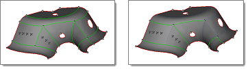
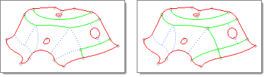
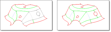
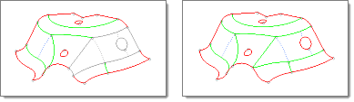
Use this subpanel to combine surfaces based on geometric features. Edges meeting the criteria specified on this subpanel will be suppressed so that the corresponding surfaces are treated as being continuous by the meshing engine. Edges falling outside the criteria remain unmodified. The angle surfs and offset surfs values preserve green edges between surfaces whose break angle (difference in surface normal direction) is more than the input value, ensuring that features are not suppressed. These normals are calculated and compared at an offset distance from their common shared edge. You can adjust both the angle and the offset distance.
With all surfaces selected, the suppressed (dotted line) edges on the right side become
Panel Inputs
|