The Binder panel lets you create a developable binder that is flat or has a single curvature. You can also edit the geometry of an existing binder.
Location
From the toolbar, select Geometry > Binder.
User Profiles
Incremental RADIOSS
Incremental LS-DYNA
RADIOSS One Step
Die Module
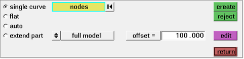
| 1. | Select the single curve subpanel. |
| 2. | Click the User Views icon  and set the view to either left or right. and set the view to either left or right. |
| 3. | Pick the locations where you want to generate one, two, or more temporary nodes. |
If you select one or two nodes, a flat binder is created. If you select three or more nodes, a ruled surface is created based on a spline passing through the nodes.
| 4. | Toggle to select either a full or half symmetric model. |
If creating a half symmetric model:
| - | Specify a vector with the the plane or vector collector. |
| - | Specify the offset value to determine the amount by which the binder outline is larger than the part outline. |
| - | Review the binder surface. To modify the binder, select edit, and make changes as needed. |
If creating a full model:
|
| 1. | Select the flat subpanel. |
| 2. | Click the User Views icon and set the view to either left or right. |
| 3. | Pick the locations where you want to generate one or two temporary nodes. |
If one node is selected, a plane surface is generated that is perpendicular and horizontal to the screen. If two nodes are selected, a plane surface is generated perpendicular to the screen and passing through the two nodes.
| 4. | Toggle to choose either full model or half symmetric model. |
If creating a half symmetric model:
| - | Specify a vector with the the plane or vector collector. |
| - | Specify the offset value. |
| - | Review the binder surface. To modify the binder, select edit, and make changes as needed. |
If creating a full model:
|
Select a binder surface, and then select edit. A new panel opens with options for editing the binder:
Select binder on section and the following options appear for editing:
Option
|
Description
|
identify binder
|
On the model graphics, select a binder surface.
|
create section
|
Create a section by intersecting a plane defined with the binder. The resulting section lines are available for editing.
|
edit section
|
2D edit: Select this option for editing a section in a 2D plane with the Section Editor.
3D edit: Select this option to modify a 3D shape of a section. Morphing handles appear on the section for manipulating the shape.
|
cast section
|
| 1. | On the model graphics, select the section that you want to cast. |
| 2. | On the model graphics, select the candidate section for modification. |
|
map to section
|
| 1. | On the model graphics, select sections to define the shape of the binder. |
| 2. | Click preview, review the shape of the binder, and then modify the shape as needed. |
| 3. | To confirm the shape of the binder, click accept. |
|
|
| 1. | On the left of the Binder panel, select part on binder. |
| 2. | Select the surface of the part that needs to coincide with the binder, and pick any nodes on the binder that do not move. |
| 3. | Click preview, review the shape of the binder, and then modify the shape as needed. |
| 4. | To confirm the shape for the binder, click accept. |
|
On the left of the Binder panel, select manipulate binder. Options appear to translate, rotate or scale the binder surface.
|
|
See also
Alphabetical List of Panels


