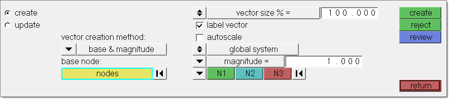
The Create subpanel offers four vector creation modes.
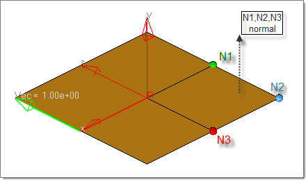
Using base and magnitude, select one or more nodes at which to place vector entities. Specify the vectors by entering x, y and z components or by using the vector method. For the vector method a user needs to specify a magnitude and a direction. The direction is determined with a standard plane and vector selector by choosing two or three nodes (N1, N2, and N3), selecting a global axis, or picking another vector. When using the N1, N2, and N3 option, two nodes specify a vector along the selected nodes, while three nodes specify a vector that is perpendicular to the plane defined by the selected nodes (using the right hand rule).
A vector can also be created by simply selecting two nodes using the vector creation method two nodes. No additional input required in this case.
The cross product option derives a vector from two existing vector entities. The vector will be perpendicular to these vectors. The length can be entered or taken from either one of the selected vectors.
Vectors can also be created using the on geometry option. You can choose to create a vector as a tangent of a line or along a normal of a surface. The resulting vector(s) will be created on all nodes selected in this panel. The length of the vector needs to be entered in vector size % = field or can be calculated automatically using parameterization. For a curve tangent this is the value of parametric curve derivative; for a surface normal the value is defined by the length of the cross product of the surface parametric derivatives.
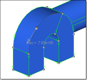
This picture shows a vector created on a line. The vector represents the tangent of the line in the node selected by the user. In some cases it can be helpful to activate the Show line directions option in the Visualization Options ( ) when using this functionality. ) when using this functionality.
|
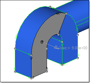
This picture shows a vector created on a surface. To predict the direction of the vector you can use the Normals panel.
|
Panel Inputs
Input
|
Action
|
vector creation method
|
This option offers four settings:
Depending on your selection the appearance of the panel will change, as described above.
|
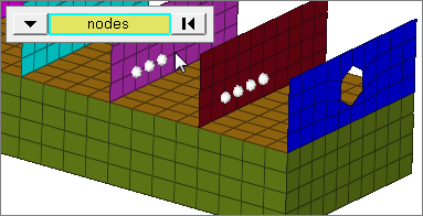
base node: nodes
|
This entity selector is only available if the base and magnitude creation method is selected. Select all nodes where you want a vector to be created.
Click the switch to change the selection mode.
nodes
Select individual nodes.
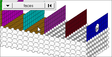
faces
Select all of the nodes on 2D and 3D faces.
If there are discontinuities on a 2D face, then only the nodes inbetween the discontinuities will be selected.
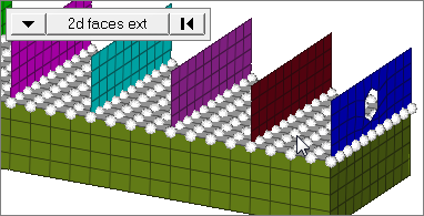
2D faces ext
Select all of the nodes on a 2D face that contain discontinuities.
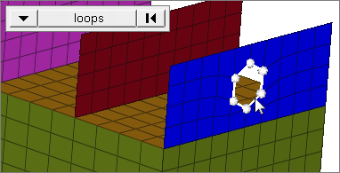
loops
Select all of the nodes on continuous free edges that make a closed loop simultaneously, such as the perimeter of a hole.
Only valid for SHELL elements.
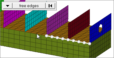
free edges
Select all of the nodes on free edges of elements.
If there are discontinuities on an edge, then only the nodes on the free edges inbetween the discontinuities will be selected.
Only valid for SHELL elements.
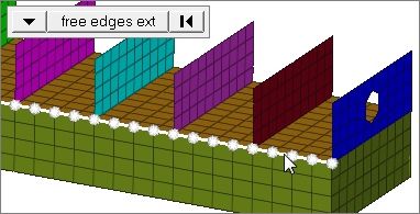
free edges ext
Select all of the nodes on free edges of elements that contain discontinuities.
Only valid for SHELL elements.
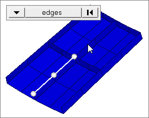
edges
Select all of the nodes on free edges or shared edges (butt joints, L/corner joints, and T-joints) of elements.
If there are discontinuities on an edge, then only the nodes on the edge inbetween the discontinuities will be selected.
Only valid for SHELL elements.
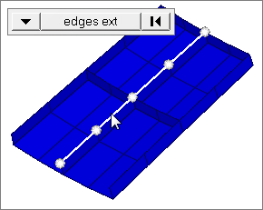
edges ext
Select all of the nodes on free edges or shared edges (butt joints, L/corner joints, and T-joints) of elements that contain discontinuities.
Only valid for SHELL elements.
|
face angle / individual selection
|
Face angle
Value used to determine which of the selected elements are to have vectors applied. For vectors applied to faces, once the starting face has been identified, the normals of the adjacent remaining faces are tested. If the angle between the normals is less than the face angle, a vector is applied to the adjacent element. This process continues until all of the free faces have been tested. For a vector applied to edges, the process is similar except that the angle between edges is used instead of the angle between faces.
Only available when the selection mode is set to faces, 2d faces ext, free edges, free edges ext, edges, or edges ext.
Individual Selection
Select individual elements on a face or select individual free/shared edges of elements.
Only available when the selection mode is set to faces, free edges, or edges.
|
edge angle
|
Splits edges that belong to a given face.
When the edge angle is 180 degrees, edges are the continuous boundaries of faces. For smaller values, these same boundary edges are split wherever the angle between segments exceeds the specified value. A segment is the edge of a single element.
Only available when the selection mode is set to free edges, free edges ext, edges, or edges ext.
|
from node / to node
|
Create a vector by selecting two nodes if the two nodes vector creation method is set.
|
base node: node
|
Input for the cross product creation method: Select a node for the vector location. One vector can be created at a time.
|
vector A: vector
|
Select vector A as input for the cross product vector creation method.
|
vector B: vector
|
Select vector B as input for the cross product vector creation method.
|
lines/surfaces
|
The on geometry creation method allows deriving vectors from either lines or surfaces.
| • | lines: Vectors will be created in the tangent of the line at the selected node position. |
| • | surfaces: Vectors will be created in surface normal direction. |
|
nodes
|
For the on geometry creation method, select all nodes where a vectors need to be created.
|
vector size % = / uniform size =
|
This setting does not affect the vector, only the length of its graphical representation. Use the toggle to choose between these options, then type in a numeric value.
| • | vector size % = sets the indicator to a percentage of the actual length of the vector (100% default). This option produces indicators of varying lengths since it depends on the vectors length at any given element. |
| • | uniform size = sets the indicators to a size that you specify, using the same units of measurement as the model. This produces identically-sized indicators whose length is not related to the amount of pressure. |
|
label vector
|
When this checkbox is active, labels for each of the vectors is displayed in the graphics area. Further vector display options are available in the Visualization options tab.
|
autoscale
|
Displays vectors in relation to the model size.
When enabled, the vector size fields are grayed out.
|
global system / local system
|
The global system / local system switch is only available with the base and magnitude creation method and the switch below set to vector. You can specify whether the vector is created either in the global or a local coordinate system.
Example: You select three nodes N1, N2 and N3 which define a vector in the global z-direction (normal of the plane defined by these three nodes). If the switch is set to local, the result will be a vector pointing in the z-direction of the local system.
|
vector / components (switch)
|
Set this switch to either vector or components.
If set to vector you can define a vector either by three points (N1, N2, N3), using one the global axes, or selecting an existing vector entity
If set to components, the x, y, z components (relative to the base node) can be entered directly.
|
magnitude = / vector A / vector B
|
These options specify the length of a vector created with the cross product method. Either a length can be entered directly, or inherited from one of the vectors A or B used as input.
|
magnitude = / use parameterization
|
If a vector is created on geometry, the length can be entered directly or the parametric value can be used.
| • | For a curve tangent this is the value of the parametric curve derivative. |
| • | For a surface normal the value is defined by the length of the cross product of the surface parametric derivatives. |
|
|