|
»Click here to display Table of Contents«
|

Line Drag Panel |

|

|

|

|
|
Line Drag Panel |
|
|

|

|
|
»Click here to display Table of Contents«
|
Line Drag Panel |
|
|
|
|
|
Line Drag Panel |
|
|
|
|
User Profiles: |
Die Module |
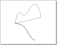
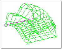
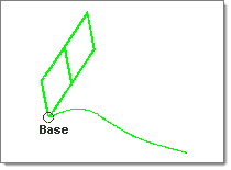
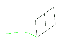
Use the Line Drag panel to create a two- or three-dimensional surface and/or mesh or elements by dragging nodes, lines, or elements along another line. An example of its use is illustrated in the design of an exhaust pipe. You can create a cross section of the pipe and drag it along the curved line which represents the pipe. Another example of its use is in the design of a window frame. A cross section of the molding can be created and dragged along the complex curves of the frame.
The Line Drag panel contains the following subpanels and command buttons:
Use the Drag Geoms subpanel to drag existing geometry such as lines.
Panel Inputs
CommentsThe orientation vector is used to orient the line being dragged to the tangent of the guide line. If the orientation vector is not initially pointing in the same direction as the tangent of the guide line, the section will be oriented. This may result in the section being rotated. To prevent the section from being rotated, select the orientation vector so that it is along the tangent of the guide line. Line segments can be used on both of the lines by selecting points on the line. Surfaces can only be created by dragging a planar line along a guide line. If the line being dragged is not planar, it is projected to the appropriate plane. The mesh w/o surf option does not have this limitation, and does not project the line being dragged to a plane. If line drag, with mesh w/o surf selected, is used before entering the automeshing module, the placement of the displayed nodes for the "along" edges gives only an approximation of where they are actually created when the mesh is generated. Indeed, the lines themselves are only approximations; if the drag is very complex, they may degenerate into a straight line. This does not affect the actual mesh.
|
Use the Drag Elems subpanel to drag existing elements.
Panel Inputs
|
The following action buttons appear throughout the subpanels:
|
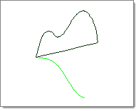
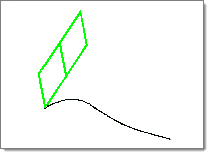
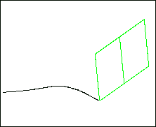
In the illustration, two lines are selected.
For information regarding the meshing options, refer to the Automeshing section of the User's Manual.
UndoClick reject immediately after creating the surface and/or mesh. To reinstate the rejected entity, click drag again, without changing any of the input data.
CommentsThe orientation vector is used to orient the line being dragged to the tangent of the guide line. If the orientation vector is not initially pointing in the same direction as the tangent of the guide line, the section will be oriented. This may result in the section being rotated. To prevent the section from being rotated, select the orientation vector so that it is along the tangent of the guide line. Line segments can be used on both of the lines by selecting points on the line. Surfaces can only be created by dragging a planar line along a guide line. If the line being dragged is not planar, it is projected to the appropriate plane. The mesh w/o surf option does not have this limitation, and does not project the line being dragged to a plane. If line drag, with mesh w/o surf selected, is used before entering the automeshing module, the placement of the displayed nodes for the "along" edges gives only an approximation of where they are actually created when the mesh is generated. Indeed, the lines themselves are only approximations; if the drag is very complex, they may degenerate into a straight line. This does not affect the actual mesh. |
or
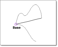
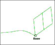
Select a base point, if required.
|
or
Select a base point, if required.
For more information on the biasing options, refer to the Element Biasing section in the Automatic Mesh Generation chapter of the User’s Manual.
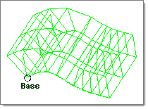
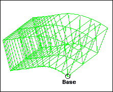
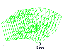
The elements in this illustration were created by using with a negative bias intensity value.
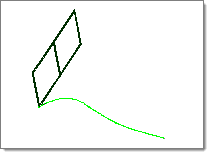
The elements in this illustration were created without element biasing.
UndoClick reject immediately after creating the elements. To reinstate the rejected elements, click drag again, without changing any of the input data.
CommentsThe orientation vector is used to orient the line being dragged to the tangent of the guide line. If the orientation vector is not initially pointing in the same direction as the tangent of the guide line, the section is automatically oriented. This may result in the section being rotated. To prevent the section from being rotated, select the orientation vector so that it is along the tangent of the guide line. A line segment can be used for the guide line by selecting points on the line. |