|
»Click here to display Table of Contents«
|

Normals Panel |

|

|

|

|
|
Normals Panel |
|
|

|

|
|
»Click here to display Table of Contents«
|
Normals Panel |
|
|
|
|
|
Normals Panel |
|
|
|
|
User Profiles: |
Incremental_RADIOSS Incremental_LS-DYNA RADIOSS One Step Die Module |
Use the Normals panel to display and reverse the normals of elements or surfaces. The orientation of element normals can also be adjusted. The normal of an element is determined by following the order of nodes of the element using the right-hand rule.
For the Abaqus interface this panel can be used to adjust or reverse the stacking direction of continuum shells.
The Normals panel consists of two subpanels for adjusting element and surface normals.
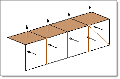
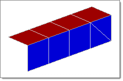
Normals can be reviewed showing a vector or by colors. A vector shows in positive normal direction, while the color mode shows the positive side of a shell or surface in red and the negative side in blue.
Normals using vectors (for explanation purposes some elements have been set to transparent mode) |
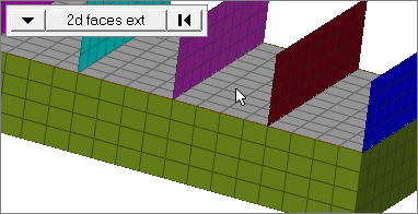
Normals using colors (red = positive and blue = negative) |
The Normals panel contains the following subpanels:
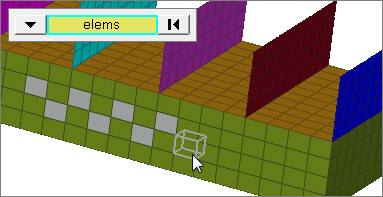
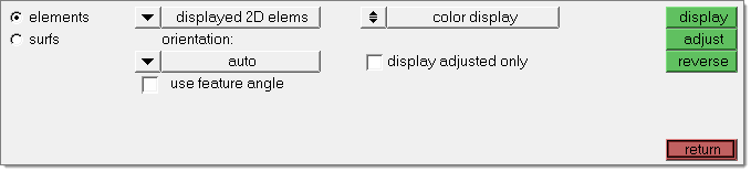
Use the Elements subpanel to display and reverse the normals of elements. Select elements indirectly by components or directly by elements, or elect to have all of the displayed 2D elements selected automatically. Click display to review the current normal orientation of the selected elements. Optionally, click reverse to flip the normals to the opposite side (reverse the normals). You can also use the Elements subpanel to adjust element normals. Select elements to adjust, then select an orientation method which determines how element normals are adjusted. When you are finished, click adjust. Optionally, select display adjusted only to only display the elements which have been adjusted in this operation. All elements selected for adjusting must be in a continuous mesh for this operation. On review, normals are displayed with vectors by default. Alternatively, you can choose to display normals in color mode by switching the toggle from vector display normals to color display normals. Normals pointing in the wrong direction can be spotted easier in bigger meshes when using the color display mode. Red indicates the positive normal direction and blue indicates the opposite side of the element. In vector mode, specify the size of normals in the size field. If this value is zero, the normal is sized based on the smallest side of the element. If a value other than zero is specified for size, the normal is drawn based on the length specified in model units. The elements subpanel is also made available in the composites panel on the 2D page.
Panel Inputs
|
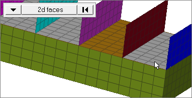
Use the Surfs subpanel to display and reverse normals of surfaces. Select surfaces indirectly by components or solids or directly by surfaces, or elect to have all of the displayed surfaces selected automatically. Click display to review the current normal orientation of the selected surfaces. Optionally, click reverse to flip the normals to the opposite side (reverse the normals). After clicking display or reverse, the normals will either be shown as vectors or in color mode, depending on the setting of the vector display normals/color display normals toggle. Adjust the vector size by entering a value in the size field. The vector will either be drawn in model units based on the value or the vector size will be 10% of the screen if zero is entered. The minimum set of surfaces required is automatically adjusted to maintain overall consistency of the surface normals, without affecting other surfaces, based on the input surface selection. The minimum set of surfaces is found from all surfaces attached by shared edges. This includes the entire surface shell, not just the adjacent surfaces. This prevents problems that can arise from incorrect or inconsistent orientations. This task can be performed in three panels: Normals, Surface Edit (offset subpanel), and Midsurface (create subpanel, solid option). In each of these panels, you can first view the surface normals by clicking show normals. You can also choose between vector display and color display of normals.
Panel Inputs
|
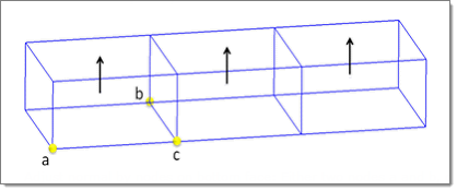
Additional functionality in the normals panel is available for the Abaqus interface if entered through the Composites panel of the 2D page. This helps to set up models using continuum shell elements. It applies to elements with the HyperMesh configurations penta6, penta 15, hex8 and hexa20. When display is clicked, the default stack direction is displayed without considering the property assigned to the underlying elements. The review is based on the numbering scheme of the continuum shell element. The display stack direction button shows the stack direction of all selected elements considering the setting of the elemental property. Supported are all three isoparametric directions as well as the definition by a system (*ORIENTATION). Normals are either displayed as vectors, or colors when in the color display normals mode (the bottom face shows in blue, and the top face in red). You have two options to use adjust normal:
Adjust normal by nodes on bottom face: Either two nodes a and b, or an additional Reverse normal and reverse stack direction return the stacking direction to the opposite. Adjust normal and both reverse functions affect the element numbering. Applied loads are automatically corrected upon adjustment to apply to the correct face of the element.
|
HM-3300: Quality: Checks and Editing