Manufacturing Solutions

Edit Element Panel

Edit Element Panel

Previous topic Next topic Expand/collapse all hidden text  

Edit Element Panel

Previous topic Next topic JavaScript is required for expanding text JavaScript is required for the print function  

User Profiles:

Incremental_RADIOSS

Incremental_LS-DYNA

RADIOSS One Step

Die Module

Use the Edit Element panel to hand build, combine, split, or modify elements.

Some of the use cases for this panel include:

Stitching two unconnected meshes by adding elements between them
Splitting elements at weld locations
Combining and splitting elements to fix connectivity in the transitional area between fine and coarse mesh areas


Panel Usage


The Edit Element panel is split into several subpanels. The entry criteria on each subpanel is retained until you leave the panel, so you will not lose data by switching from one subpanel to another.  The panel is organized into four columns, with subpanels listed in the first column on the left hand side.  Each subpanel includes a means of selecting the elements to be edited located in the second column directly next to the subpanel list, with any additional criteria (if necessary) following in the third column.  The fourth column on the right-hand side contains the buttons used to execute commands or exit the panel.

edit_element_panel


Subpanels and Inputs


The Edit Element panel contains the following subpanels and command buttons:

expand-green-10Create

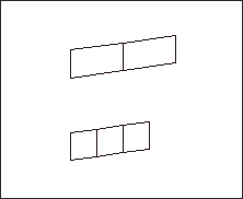
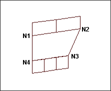
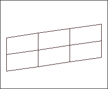
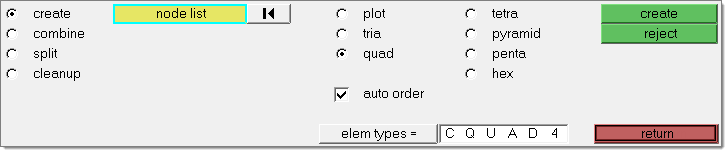
use the Create subpanel to you to create elements manually by selecting nodes. For example, you can use this subpanel to build elements in a situation where three elements are to be joined with two elements. You can create multiple plot elements by selecting by path from the node list selector. The element type is selected, followed by the selection of nodes to create the element.  The element is automatically generated as soon as the required number of nodes for the chosen element type is selected.  After at least two or more nodes are selected, clicking the middle mouse button or the green create button creates whatever element type is appropriate for the number of nodes selected.  

For example, while creating quads, you need to create one tria.  You can leave the element type as quad, select three nodes, and then click the middle mouse button to complete the selection.  A tria element is generated.  Similarly, while creating a hexa element, you can create any lower element type without changing the element type to be created.

When creating second order elements, make sure you set element order: in the Options panel's mesh subpanel.


Panel Inputs

Input

Action

node list

A group of nodes from which you wish to create an element.

plot, tria, quad, tetra, pyramid, penta, hex

Use these radio buttons to choose the type of element you wish to create.

auto order

The mesher will attempt to determine the node order automatically; if this is not selected, you must select the nodes in the appropriate order.

This option may re-sequence the selected nodes to prevent the creation of inverted or folded elements.

elem types =

For elements using a solver card image, click this button to open a menu of available types and select the type you wish to create.


expand-green-10Combine

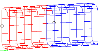
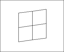
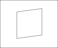
Use the Combine subpanel to you to combine two or more shell elements into a single quad or tria element, or combine 1D elements into larger 1D elements to coarsen a 1D mesh. The number entered for auto comb = determines the required number of elements that must be picked before the combined element is automatically generated.  You can also use the middle mouse button after the elements are selected (even if you pick fewer than the auto comb = number) to proceed to combine the elements.


Panel Inputs

Input

Action

elems

Use this collector to specify the elements you wish to combine.

combine to quad / combine to tria

This setting determines what type of elements result from the combination.

tolerance =

This is a planar tolerance angle; elements deviating from a plane by this degree or greater will not be combined.

auto comb =

Auto Combine--as you click to select elements, each time you have selected this number of elements they will be combined automatically. To disable auto-combine behavior, enter a zero in this field.


expand-green-10Split

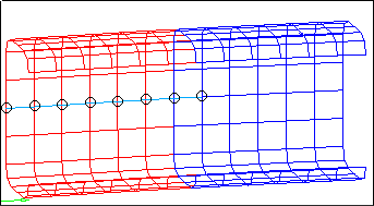
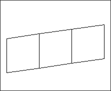
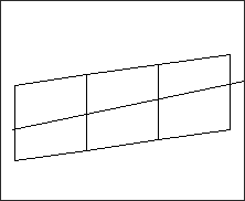
Use the Split subpanel to split 1D and 2D elements, either singly or in a group.  You must first select the elements to be split (or toggle to displayed elems to consider all elements in the display for splitting), then select the split-line points along which you wish to split the elements. To split an element, the split line must cross that element’s boundary; where the split line crosses the element boundary determines how it will be split. If the split line crosses near a corner vertex, the split will be snapped to that node. If the split line crosses near the midpoint between two corners, a node will be added at the exact midpoint and the split will occur there.

When splitting shell elements that have 1D elements along their edges, check the Consider 1Ds also option to also split the attached 1D elements.

Note:This split function does not split 3D elements, nor does it split the elements at the exact location of the line. It can only split an element through the corner (node) or the middle of an element side (mid-node) in order to retain connectivity of the model.


Panel Inputs

Input

Actions

displayed elems / elems / comps

Determines whether the split action will affect all elements currently displayed, specific elements chosen by you, or the elements of specific components chosen by you.

If you pick elems or comps, an entity collector displays so that you can select the desired elements or components.  When set to displayed elems, all elements in the current display are considered for splitting.

Splitting line

When this box is highlighted (click it if it is not), you can draw a line of one or more segments in the graphics area. Elements will be split along this line when you click the split button.  Each left-click lays down a point along the line.  Right-click to remove the most recent point.  There is no need to "finalize" the line series--it will persist until you click either the split button, or the delete line button.

Consider 1Ds also

1D elements will also be split, provided they fit the element selection criteria (visible, or selected, or part of a selected component).


expand-green-10Cleanup

Use the Cleanup subpanel to select elements to clean up. Once selected and you click the cleanup button, a new secondary panel displays element criteria and cleanup tools.  Selected elements are color coded based on how well or badly they fit the chosen criteria, and you can manually place nodes or perform an automated cleanup algorithm on the elements.


Panel Inputs

Input

Actions

displayed elems / elems

Choose between cleaning up all displayed elements, or only specific elements that you select.  If you pick elems, an entity collector displays so that you can pick the specific elements you wish to clean up.


expand-green-10Command Buttons

The following action buttons appear throughout the subpanels:

Button

Actions

create

Create the element

reject

Reverts the most recent action, or clears the current selection.

combine

Combines the currently selected elements.  This will only be necessary if you have disabled auto-combine, or wish to combine a number of elements that is less than the value of auto comb =.

split

Performs the split.  Elements that the line passes through are split into two or more smaller elements.

delete line

Deletes the current splitting line.

return

Exits the panel.


hmtoggle_arrow1Cleanup Secondary Panel Input

Panel Inputs

Input

Actions

max angle, warpage, jacobian, skew, length

Element quality checks as defined in check elems panel.  You can select any combination of checks from this list. Elements that you have selected are color coded according to how well they fit the checks that are selected here:

Red: the element fails at least one of the specified checks.
Yellow: The element passes all checks, but is marginal (poor quality) on at least one.
no color: no problems are detected.

node (place node)

When this is active, left-click and drag an existing node to reposition it.  The affected elements' color coding changes dynamically as you drag the node.  Release the mouse button to set the node at its new location.

edge (swap edge)

When this is highlighted, click an edge to swap it between its possible locations.  The number of legal positions for an edge depends on the type of elements that it lies between:  For a pair of trias, there are two possible positions for their shared edge.  For a pair of quads, there are three possible positions.  For a quad and a tria, there are six possible positions.  Each time you pick the edge, it switches to the next legal configuration.

smooth

This button executes an automatic smoothing algorithm over all of the selected elements.  The behavior of this process is affected by the autodecide, size corrected, shape corrected setting below.

autodecide, size corrected, shape corrected

Use this switch to affect the behavior of the smooth function.

shape corrected: The elements will be modified with an eye toward trying to keep a uniform element size.
size corrected: The elements will be modified with an eye toward trying to keep an ideal element shape.
autodecide: the algorithm will decide dynamically for each element whether size or shape optimization is best.

undo

Reverts the most recent cleanup action, including the automated smooth process.

redo

Performs the most recently undone cleanup action.

abort

Discards all changes made to the mesh and returns to the cleanup subpanel.


How do I...

expand-green-10Build an element
1.Select the create subpanel.
2.Select the type of element that you want to create.
3.Click auto order if you want the nodes ordered for you.

If it is not selected, you must select the nodes in the appropriate order.

4.Select the nodes of the element you want to create.

HM_Panels_bmp00105

When you have selected the required number of nodes, the element is created.

HM_Panels_bmp00106


Undo

Click reject or click the right mouse button to reject the last element you created.


Comments

If the auto order option is off, you must select the corner nodes first, followed by the mid-side nodes, when you build second order elements.

The element is automatically generated as soon as the required number of nodes for the chosen element type is selected.  You can create other elements in the same category (2D and 3D categories) by using the middle mouse button.  For example, while creating quads, you need to create one tria.  You can leave the element type as quad, select three nodes, and then click the middle mouse button to complete the selection.  A tria element is generated.

In this subpanel, the status bar continually displays messages, so no menu title is shown.

expand-green-10Build plot elements
1.Select the create subpanel.
2.Select plot as the element type you want to create.
3.Click node list and select by path.
4.Select the nodes that define the path.

edit-ele-1

HyperMesh automatically picks all the nodes in the path and creates plot elements between each set of consecutive nodes in the node path.

edit-ele-2


Undo

Click reject.

expand-green-10Combine elements
1.Select the combine subpanel.
2.Click the toggle to combine to quad or combine to tria to specify how you want the elements to be combined.
3.Select the elements you want to combine.

HM_Panels_bmp00107

4.To change the planar tolerance, or to automatically combine a set number of elements, select those items and enter the appropriate values.
5.Click combine or click the middle mouse button.

HM_Panels_bmp00108


Undo

Click reject immediately after combining the elements.


Comments

When elements are being combined, HyperMesh requires the nodes attached to the elements to be planar within a user-specified tolerance. The tolerance may be changed with the menu item tolerance =.

This operator works with two-dimensional, first and second order elements.  If you select second order elements, the new element is second order.

You may automatically combine a set number of elements.  Click auto comb = and enter the number of elements you want to combine.  HyperMesh automatically combines the elements after the number of elements you select equals the number of elements specified by auto comb =.

expand-green-10Split elements
1.Select the split subpanel.
2.Indicate which elements you want to split by selecting them on your model, selecting displayed elements using the collector selector, or click elems and select from the extended entity selection menu.

HM_Panels_bmp00109

3.Click points (of split line) or click the middle mouse button.
4.Use the mouse to build a line in the graphics region which intersects the elements you want to split.

HM_Panels_bmp00110

5.Click split elements or the middle mouse button.

HM_Panels_bmp00111


Undo

Click reject immediately after splitting the element(s).


Comments

This operator works with two-dimensional, first, and second order elements.

Elements are split either at the mid-side or corner nodes depending on how the line/window built intersects the element(s).


See also

Check Elems panel

Alphabetical List of Panels