Manufacturing Solutions

Reflect panel

Reflect panel

Previous topic Next topic Expand/collapse all hidden text  

Reflect panel

Previous topic Next topic JavaScript is required for expanding text JavaScript is required for the print function  

User Profiles:

Incremental_RADIOSS

Incremental_LS-DYNA

RADIOSS One Step

Die Module

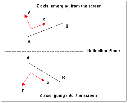
Use the Reflect panel to reflect portions of a model about a plane, changing the selected portion into a mirror image of itself.

Notes

To undo a reflection, simply click reflect again without changing any other settings.
Nodes located on the plane of reflection are not equivalenced.  This function is available in the Edges panel.
Loads, constraints, and systems attached to the reflected structure move to the new location of the parent entity, but they are not reflected.
Local coordinate systems can be used to define the plane of reflection by using the vector option and selecting one of the vectors defining the local system.
Reflecting surfaces separately from the nodes or elements built on them breaks association with those nodes/elements.  Reflecting surfaces back to their original position will not restore these associations, but they can be restored via the Node Edit panel.
When reflecting a component, all of the geometry (lines, surfaces, connectors, and points) and elements (nodes) contained in each component are reflected with the component, and associations are maintained.


Subpanels and Inputs


There are no subpanels on the Reflect panel. All inputs and command buttons are located on the main panel.


Panel Inputs

Input

Action

(entity selector)

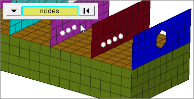
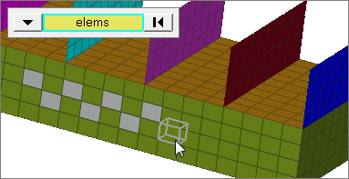
Used to select entities for reflection. Valid entity types include nodes, elements, components, lines, surfaces, points, solids, and connectors.

When you select nodes or elems, click the switch to change the selection mode.

nodes

Select individual nodes.

faces_edges_nodes

faces

Select all of the nodes on 2D and 3D faces.

If there are discontinuities on a 2D face, then only the nodes inbetween the discontinuities will be selected.

faces_edges_faces_nodes

2D faces ext

Select all of the nodes on a 2D face that contain discontinuities.

faces_edges_2d_face_ext_nodes

loops

Select all of the nodes on continuous free edges that make a closed loop simultaneously, such as the perimeter of a hole.

Only valid for SHELL elements.

faces_edges_loops_nodes

free edges

Select all of the nodes on free edges of elements.

If there are discontinuities on an edge, then only the nodes on the free edges inbetween the discontinuities will be selected.

Only valid for SHELL elements.

faces_edges_free_edges_nodes

free edges ext

Select all of the nodes on free edges of elements that contain discontinuities.

Only valid for SHELL elements.

faces_edges_free_edges_ext_nodes

edges

Select all of the nodes on free edges or shared edges (butt joints, L/corner joints, and T-joints) of elements.

If there are discontinuities on an edge, then only the nodes on the edge inbetween the discontinuities will be selected.

Only valid for SHELL elements.

faces_edges_edges_nodes

edges ext

Select all of the nodes on free edges or shared edges (butt joints, L/corner joints, and T-joints) of elements that contain discontinuities.

Only valid for SHELL elements.

faces_edges_edges_ext_nodes

elems

Select individual elements, or select all of the elements contained by a component or on a surface.

faces_edges_entities

faces

Select all of the elements on 2D and 3D faces.

If there are discontinuities on a 2D face, then only the elements inbetween the discontinuities will be selected.

faces_edges_faces

2D faces ext

Select all of the elements on a 2D face that contain discontinuities.

faces_edges_2d_faces_ext

(plane selector)

Used to define the plane of reflection.

When using the N1, N2, N3 option you can either define a plane (N1, N2, N3) or define a vector using two nodes (N1 and N2)--in which case the reflection plane is normal to the specified vector.
You can also use other vectors (coordinate system axes or vector entities) to define the reflection plane.  In such cases the plane is normal to the selected vector.
A base node is required because it defines the location of the plane.  If you do not specify one while using the N1, N2, N3 method, N1 is used as the base node.

Bar Elements

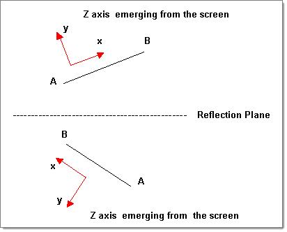
This toggle appears when you select elems or comps from the entity selector.  Use it to determine how bar elements are reflected: by maintaining the z-axis direction or by maintaining the element connectivity.

reflect1b

Maintain Z axis

reflect1a

Maintain element connectivity

face angle / individual selection
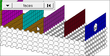
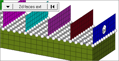
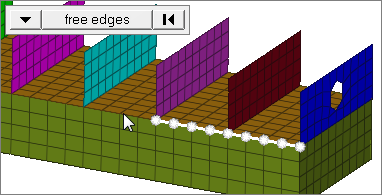
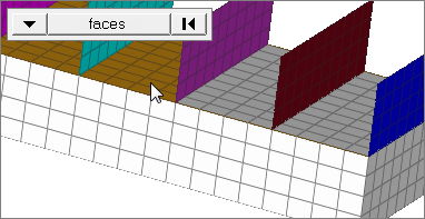
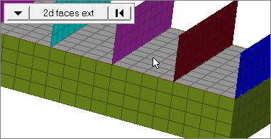
Face angle

The face angle is the angle between the normal of facets that share an element edge. A facet can either be a shell element itself, or one of the faces of a solid element. The normal of triangular facets is that of the plane defined three corner vertices. Whereas, the normal of quadrilateral facets is calculated by taking the cross-product between its two diagonals. This special treatment for quadrilaterals is because a warped shape does not lie completely on a plane.

Only available when the entity selector is set to nodes or elems and the selection mode is set to faces, 2d faces ext, free edges, free edges ext, edges, or edges ext.


Individual Selection

Select individual elements on a face or select individual free/shared edges of elements.

Only available when the entity selector is set to nodes or elems and the selection mode is set to faces, free edges, or edges.

edge angle

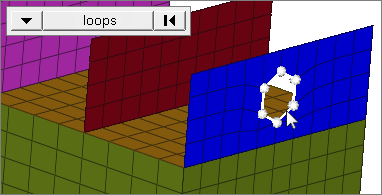
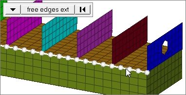
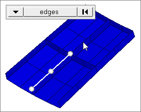
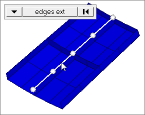
Splits edges that belong to a given face.

When the edge angle is 180 degrees, edges are the continuous boundaries of faces. For smaller values, these same boundary edges are split wherever the angle between segments exceeds the specified value. A segment is the edge of a single element.

Only available when the entity selector is set to nodes and the selection mode is set to free edges, free edges ext, edges, or edges ext.


Command Buttons

The following action buttons appear:

Button

Action

reflect

Moves the selected entities about the plane of reflection.

return

Exit the panel.


How do I...

expand-green-10Reflect data about a plane
1.Open the Reflect panel.
2.Click the entity selector switch and select the data type of the entities you want to reflect.
3.Indicate the entities you want to reflect:
Select the desired entities on your model

or

Click the data type and choose from the extended entity selection menu.

reflect1

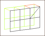
Selected elements highlight.

4.Use the plane and vector collector to indicate the plane of reflection.

reflect2

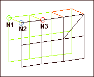
Three nodes define the reflection plane.  N1 is the base node.

5.Click reflect.

reflect3

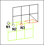
The selected elements are reflected about the plane.


Undo

Select reflect a second time, without changing any of the input data.


See also

An Alphabetical List of Panels

*reflectmark()

*reflectmarkwithoption()