Generally, two guidelines should be followed when building a mismatched mesh between the tool and the workpiece:
| • | The ratio should be less than 1:20. That is, one coarse element on the tool side should not be in contact with more than 20 elements on the workpiece side. |
| • | Mesh on either side should be fine enough to follow the curvature. |
Typically, a model has large curvature in only one plane, as dictated by the profile geometry. Try to follow the curvature on that plane; the mesh can always be coarsened in the extrusion direction (typically Z), along which the mesh is dragged.
The following examples demonstrate mismatch ratios, curvature tolerances, and overlap.
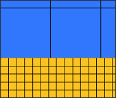
Example 1: Acceptable Mismatch Ratio
The following mesh is good because for every element on the tool side, there are about 6 to 7 elements on the workpiece side, which is an acceptable ratio.
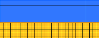
Example 2: High Mismatch Ratio
The following mesh shows more than 20 elements on the workpiece side for every element on the tool side. This ratio is unacceptable and will lead to incorrect results.
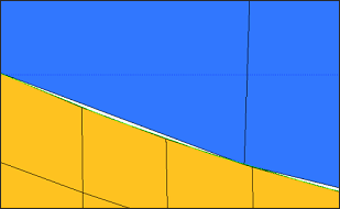
Example 3: Acceptable Curvature Tolerance
In the following mesh, a crack exists between the tool and the workpiece elements. The tool elements do not follow the curvature. If the gap is less than 2.5 percent of the element size on the workpiece at the center of the face, the mesh is acceptable and the gap between the elements is within the tolerable limits.
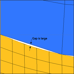
Example 4: Unacceptable Curvature Tolerance
In the following mesh, a large crack exists between the tool and workpiece elements. The tool elements do not follow the curvature. Some of the workpiece elements will not correctly identify the tool element, leading to incorrect results.
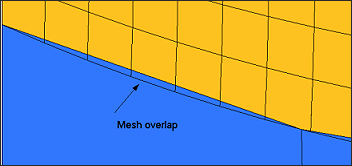
Example 5: Acceptable Overlap
Depending on the curvature of the model, tool elements might overlap the workpiece elements. Overlap is acceptable when the overlap does not extend past one full element. Even if the overlap extends beyond one element, element detection is not affected. Only the accuracy of the results is impacted.
See Also:
Guidelines for Simulation


