The next checkbox in the Extrusion Wizard is Generate Workpiece Mesh.
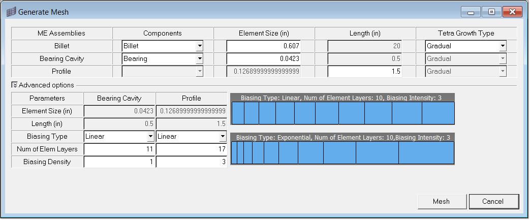
If you start with solids, then this macro will be used to generate mesh. It requires you to identify the components in which solids are stored for each assembly, element size for each component and in the case of Profile, length of the profile. You can select the Tetra growth type which has options Gradual, Interpolate and Standard. This selection is valid only for solids that are tetmeshed. Please refer to the tetmesh help for detail descriptions of these options. In general, interpolate will create a finer mesh, and standard will produce a coarser mesh. Gradual is the most optimal choice.
For Bearing and Profile, you can set the Biasing Type, Element Layers and Biasing Density. Biasing type has options Linear and Exponential. The images below show sample mesh for these biasing types. Please note that these images are provided only give you an idea how linear and exponential differ; and these images do not dynamically change to reflect your current selection. These features help you to control the mesh quality. For most models, default options should work fine.
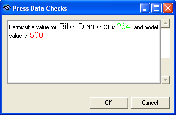
If a press is selected, clicking Mesh enables press data checks, which are shown in a separate window.
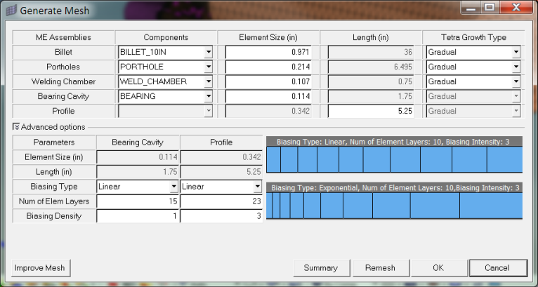
After the initial mesh is created, you will be prompted to accept it or remesh. You can inspect the model, change meshing options and remesh if needed. Clicking Remesh will delete the existing 3D mesh and regenerates the 3D components with modified element sizes. If the mesh is acceptable, click OK to proceed further.
It is important to note that the names used for the component collectors containing the solids should not end with the suffix 3D. This is because HyperXtrude uses some standard names such as Billet3D for the components containing 3D elements that are automatically created by the wizard. On Remesh command, the wizard will delete all these 3D components. If solids in the geometry contain the names with suffix 3D, they may also be deleted and you may lose your CAD data.
If you start with an existing mesh, you will have to indicate the components that have the mesh for each extrusion component, such as billet. This will be explained in subsequent sections.


