This subpanel creates surfaces that closely fit a selection of shell elements.
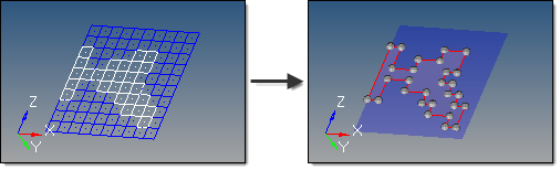
In this example the mesh is changed from wireframe to transparent to make the surface more visible.
Six inputs are required to create a surface using this method:
| • | The shell elems that are to be used to generate surfaces. In order to create surfaces from solid elements, create faces using the Faces panel and select the elements in the ^faces component. |
| • | The auto detect features and feature edges options define whether features (surface edges) are automatically determined, or whether they are specified by 1D plot elements (features). |
| - | If set to feature edges, 1D plot elements must be selected to represent the edges of the surfaces to be created. It is recommended to select a closed loop of plot elements in order to best guide the algorithm. Features can be created using the Features panel. |
| - | The algorithm used by this function tries to subdivide shell elements into subsets if it does not succeed in creating a single surface through the selected shell elements. |
| • | The mesh based auto tol / tolerance options define how closely the new surfaces adhere to the underlying elements. The tolerance value is the maximum distance by which the surface created differs from the selected elements at any location. This is particularly important for curved meshes. |
| - | The mesh based auto tol option calculates the tolerance based on the average element size of the selected elements. |
| - | The tolerance option allows a value to be entered manually. A smaller tolerance usually results in a larger number of surfaces created. |
| • | The surface complexity option affects how many surfaces are created. This option takes into account a number of factors, including the boundary shape of the area to be surfaces as well as its topology. Higher complexity values create a smaller number of more complex surfaces, but require longer calculation times to create those surfaces. Smaller values produce a larger number of smaller, simpler surfaces, but do so more rapidly: |
| - | When the complexity is set to 1 (simplest surface), the function attempts to create surfaces with few control points. If it fails, it tries to subdivide the selected elements until it can fit a lower order surface definition to the elements. |
| - | When the complexity is set to 10 (complex surface), the function first attempts to create surfaces with as few control points as possible. If it fails, it continues to increase the number of control points and attempts to fit one surface between the selected groups of elements. It will not try to automatically subdivide the elements. |
| - | The recommended complexity value is 5. |
| • | The split by components option maintains boundaries between adjacent components, so that a single mesh plane will still produce separate surfaces based on the components that the elements belong to. |
| • | The associate nodes option ensures that the mesh nodes are associated to the new corresponding surfaces. This allows re-meshing of the surface to replace the original mesh instead of creating a new overlaid mesh. |
How do I....
Create surfaces from an FE mesh
See also
Surfaces panel


