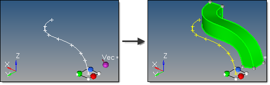
This subpanel creates solids by dragging surfaces along a line.
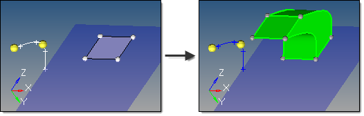
Eight inputs are required to create a surface using this method:
| • | The lines or node list to drag. |
| - | If a node list is specified, a line will first be fit through the specified nodes. |
| - | The line list that defines the lines that the drag will follow. This can also be a series of connected lines. |
| • | The merge solids at shared edges option applies when one or more input surfaces are attached to each other. This does not apply to single surface or unconnected surface selections. |
| - | If disabled, a solid is created for each input surface, with shared faces created at the shared edge locations. |
| - | If enabled, a single solid is created with merged faces created at the shared edge locations. continuous lines. |
| • | The create in method, which defines the resulting solids' component organization. |
| - | Specifying current component organizes the new solids and the selected surfaces to the current component. |
| - | Specifying surfs component adds the new solids to the same component that the selected surfaces already belong to. The result is unpredictable if surfaces from different components become a part of the same solid. |
| • | The frame mode defines how the surfaces are translated and rotated during the drag. Each of the following examples uses this starting model: |
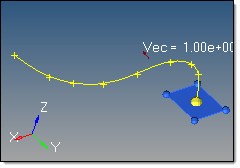
fixed frame: the surfaces are only translated during the drag, not rotated.
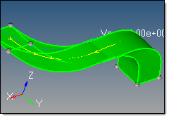
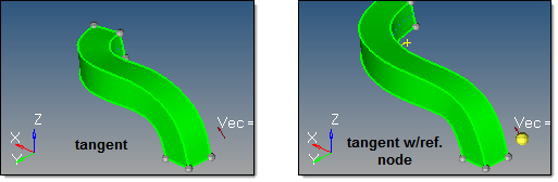
line tangent: in addition to the translation of the fixed frame option, the surfaces are also rotated in the same way that the tangent of the line list rotates.
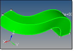
Frenet frame: in addition to the translation and rotation of the line tangent option, the surfaces also rotate around the line list tangent axis in the same way as the curvature vector rotates.
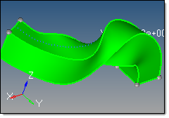
The Frenet frame option does not work well when the curvature of the line is not smooth or there are large jumps.
| • | The reference node and transformation plane options require the following definitions: |
S: start of drag line, which is the closest end of the line to the surface vertices. Drag + follows this direction. Drag - follows the opposite direction.
T: tangent of drag line at S.
R: reference node.
B: base node of the transformation plane.
N: normal vector of the transformation plane.
The reference node (R) is used to translate the drag line prior to the drag. By default, R=S. If a different S is specified, the line list is translated by the vector defined from S to R.
The transformation plane is used to translate and rotate the input surfaces prior to the drag. By default, no transformation occurs (B=R and N=T). If specified, the surfaces are translated by the vector defined from R to B, and are rotated from N to T.
| • | The direction of the drag. |
Drag + is defined at the start of drag line, which is the closest end of the line to the surface vertices.
Drag - is defined in the opposite direction.


