Bearing boundary conditions are used to define the bearing region in a metal extrusion die. HyperXtrude enables you to specify this region using a curve called a bearing profile. The region between this curve and the die face (along the extrusion axis) is identified as the bearing region. This approach allows you to have flexibility in meshing and thereby does not require the mesh to conform the contours of the bearing region. A bearing boundary condition is made of three components:
| • | A boundary face that forms the bearing region. This does not need to be exact but must be large enough to include the bearing profile. Typically, the boundary face that forms the bearing region is the boundary face of the Bearing3D region in a mesh. |
| • | Bearing boundary condition data, such as friction type and value |
The bearing region is used to control the material flow in an extrusion setup. By adjusting this region, you attempt to balance the flow exiting the die.
Follow these steps below to define a bearing profile in HyperXtrude. This procedure assumes that you have already created a boundary condition of the type Bearing and captured the boundary faces corresponding to this BC. There are two steps to this procedure after you click Create.
Step 1: Select how you want to specify the bearing line data as lines (preferred) or nodes.
Step 2: Edit the bearing table to adjust the bearing length.
Follow the steps below:
| 1. | Click Create in the Bearing BC page. You are prompted to make the selection for how you want specify the bearing line data as lines (preferred) or nodes. |
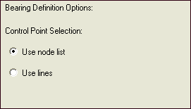
| 2. | Click Use node list and click Next. The node selection panel appears. |
| 3. | Pick nodes corresponding to the control points on the minimum Z side. For open loop bearing, pick the corner nodes at both the edges. The bearing length changes at these control points. The order in which you pick these points is not important. The macro will automatically sort it to match the node loop. After making the selections, click proceed. |
| 4. | On the next panel of the wizard, select the minimum, maximum and initial values for the control points. Minimum and maximum is automatically determined from the bearing region. These values are used to populate the table, but you can modify them individually for each node in the table. Click Next to proceed. |
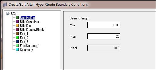
| 5. | The next panel will show all the control points and will let you control the minimum, maximum, and initial data for each point. |

See Also:
Export/Import Bearing Control Points


