Ply entities define a FEA ply which is the FEA correlation to a physical
ply.
Physical
plies manufacture laminates which make up composite structures. A physical ply has
attributes of material, shape (area), thickness, and fiber orientation; where its shape is
any complex flat pattern that can be cut from a roll of material. Similarly, a FEA ply is
composed of the same data attributes as a physical ply (material, shape/area, thickness, and
fiber orientation). The shape of a FEA ply can either be defined by closed lines or
approximated from the elements which most closely represent its actual complex shape. In the
case where plies are defined on lines, perform a realization to convert this information
into a definition by elements. Ply data defined on lines is imported from Catia Composites
Parts Design (CPD) data.
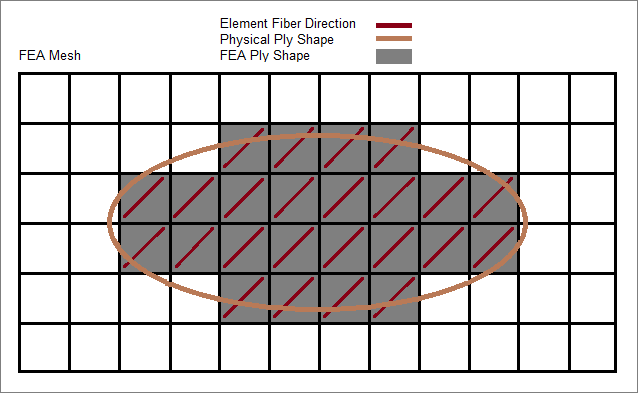
Plies defined by elements
The shape (area) of an FEA ply is defined by selecting elements which most closely
represent the complex shape of a physical ply. In Figure 1, an elliptical
physical ply shape is defined by the brown line. The corresponding FEA ply shape is
defined by the gray shaded elements of the associated FEA mesh. Typically, if an
element's centroid exists within the bounds of the physical ply shape, that element is
considered part of the FEA ply shape. Figure 1.
Plies defined by lines
Plies can be defined by selecting lines which build a closed area. If CPD data is
imported from Catia files, plies are defined on lines.
Once a mesh is available, plies defined by lines can be converted into plies defined
by elements by performing a realization. Realization/conversion methods include:
Project normal to target mesh
If the element centroid projected along its normal lies within the geometrical
ply definition, it is associated with this ply.
Normal by ply contour
Projection along a normal on a surface derived from the lines of a ply
contour.
Specified direction
Manually define a projection direction.
The ply thickness is typically defined as the final cured thickness of a single
ply of material. In addition, the ply can be made of any material: isotropic, orthotropic,
anisotropic, or any other material law. Figure 2.
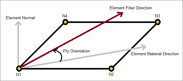
The fiber orientation of a ply defines the direction fibers lay within that
ply. The ply fiber orientation is typically an integer value between -90 and 90. The fiber
orientation of a ply is always defined relative to each elements material direction using
right hand rule around the elements normal, or thru-thickness direction, to define positive
angles. Even though a ply's fiber orientation is a constant integer, element material
directions can vary from element to element, and this allows varying fiber directions within
a ply to be modeled. Element material directions are defined differently from solver
interface to solver interface. Figure 3.
Once all of the plies which make up a composite structure are defined, just as
in the actual hand-layup manufacturing process, plies are stacked in a specific given order
within the laminate entity to define a laminate of the structure. It is possible to stack
plies, whether they are defined based on geometry or elements.
Turn the display of
plies on/off or change the way plies appear in the modeling window
with the Ply layers display setting, which can be accessed from the Mesh Display settings on
the View Controls toolbar.