The vehicle library is installed as a part of the normal HyperWorks installation.
To begin building a model, from the Model menu, select Assembly
Wizard.
Select the type of model to build and then click
Next.
Option
Description
Front end of vehicle
Builds one of the five front suspensions and corresponding
suspension subsystems (shock absorbers, springs, stabilizer bars, and so
on) and will also allow you to select an appropriate steering system to
go with the front suspension. The model can be kinematic or compliant
and will support all of the half-car analysis events, such as ride,
roll, steer and K&C.
Builds one of eleven rear suspensions (user selected) and builds the
subsystems associated with the suspensions. The model can be kinematic
or compliant and will support all of the half car analysis events, such
as ride, roll, steer and K&C.
Full vehicle
Builds a full vehicle model, with steering, front suspension, rear
suspension, powertrain, drivetrain, and tires. The full vehicle option
has a wide variety of selections which allow over one hundred thousand
different combinations to be built.
Powertrain model
Builds a rigid body engine supported by engine mounts. Longitudinal
and transverse engine configurations are supported. Standard engine
events can also be run. The events are normally used to understand
engine motion (for packaging) and engine mount forces due to the engine
torque.
Select the type of driveline to include, and click Next.
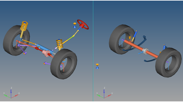
The drivetrain can be included in any front or rear suspensions. Drivetrains
are included so their motion can be studied, and also so that the loads can be
applied into the suspension via the drivetrain to simulate the true vehicle
performance. The drivetrain includes a differential, and either Hookes joints or
Constant Velocity joints where appropriate in the system. Front-wheel drive,
rear-wheel drive and all-wheel drive systems are represented. A reduction style
four-wheel drive transfer case is not included, but can be built manually in the
MotionView interface. Two different drivetrain
systems are shown in the image below:Figure 1. Left: Front Suspension with a Differential and Two Half-Shafts;
Right; Solid Axle Drivetrain with a Differential and Two Axle
Shafts
In the Car/Small truck - Primary Systems for Front end of
vehicle dialog, make the following selections:
Option
Description
Body fixed to ground
Include a vehicle body part in the model.
Instrumentation
Front Subframe
Include an isolated front subframe.
Front Suspensions
Select one of the available front suspensions.
Steering Linkages
Select one of the three types of steering systems.
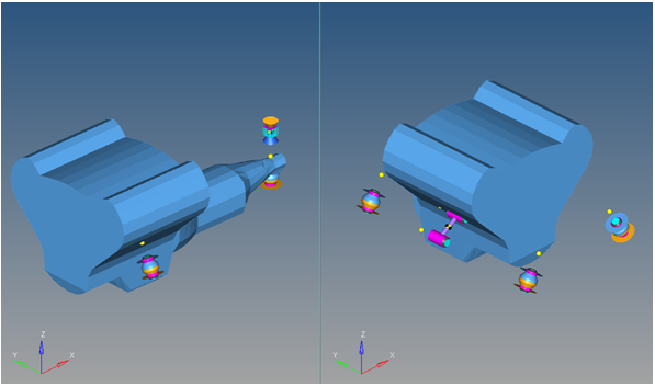
Powertrain
The powertrain consists of an engine body and a series of engine
mounts that are modeled using bushings. In transverse mounted engines,
one or more “dog bone” style mounts may be included in the model. The
event included in this model applies a torque at the transmission output
shaft. This system is designed to simulate the engine motion during
acceleration and braking events, and act as one of the building blocks
for full vehicle modeling. Figure 2. Left: Longitudinal Engine; Right: Transverse Engine
Note: Internal engine mechanisms are not modeled.
Click Next to open the Steering
Subsystems dialog, and make the following selections:
Option
Description
Steering column
Steering column 1 to include a steering
column with two universal joints.
Steering boost
Include steering system hydraulic boost effects.
Click Next to open the Springs, Dampers and
Stabars dialog, and make the following selections:
Option
Description
Front Struts
Defines the strut motion
Front Stabilizer bars
Stabar with links: A multiple-beam style stabilizer bar
Two-piece
stabilizer bar: Rotational spring to simulate the bar
stiffness
Click Next to open the Jounce/Rebound
Bumpers dialog, and make the appropriate selections.
Note: Internal bumpers are integrated into the strut. External bumpers are
separate from the strut.
Click Next to open the FWD Driveline
Systems dialog, and make the appropriate selection.
When finished building the model, the model should be displayed in the
modeling window (the part colors may vary).
Note
the following features in the resulting model:
The strut, stabilizer bar, and jounce and rebound bumper systems are
grouped under the suspension systems.
Steering is a separate system with the steering column as a
subsystem.
Individual systems can be turned on and off.
The vehicle body is a rigid body and is fixed to ground with two
separate joints, illustrated with a pair of cones.
The point names in the model correspond to industry terminology.
Modifying the point XYZ location will move the point, the joints or
bushing associated with it, and the geometry that illustrates the
parts.
The bodies have logical names. Use the browser to update their
properties.
The bushings in the model have placeholder values for
rates for both K and C in all six directions. Replace them with measured
data or estimates.
The coil spring and damper elements have estimated
values for spring rate, preload, and damping.
At this point, you have
selected all of the systems that will be in the model. You can go back and
change the selections or move forward and finish building the model with the
Attachment Wizard.